Book TOC · Previous · Chapter 3 of 8 · Next
Chapter 3: Google Kubernetes Engine (GKE) Networking: VPC-Native IPAM, Dataplane V2, Gateway API & DNS
Chapter Focus: VPC-native alias IPs, Pod/Service secondary CIDR sizing, GKE Dataplane V2 (eBPF/Cilium), NetworkPolicies, Private Clusters, Connect Gateway, Container-Native Load Balancing (NEGs), and Cloud DNS for GKE.
Subsection 1.4: Designing for Google Kubernetes Engine (GKE)
The Big Picture
Google Kubernetes Engine (GKE) is the most IP-intensive workload you will ever place inside a VPC. Whereas a standard Managed Instance Group consumes 1 IP address per VM, a single GKE worker node running at default settings claims 1 primary IP (for the node VM) + 256 secondary alias IPs (/24 for Pods)! In production, teams that design GKE networks like standard VM subnets consistently hit three walls:
- The Secondary CIDR Exhaustion Wall (
1.4c,1.4d): Unlike primary VPC subnets, secondary IP ranges cannot be expanded after creation. If a team assigns a/22secondary range for Pods ($1,024$ IPs) and leaves--max-pods-per-nodeat110, the cluster hitsIP_SPACE_EXHAUSTEDon its 5th node ($1,024 / 256 = 4\text{ nodes max}$)! Worse, if they allocate massive10.x.x.xblocks to Pods across 50 clusters, they exhaust the enterprise's entireRFC 1918address space. - The Control Plane Lockout vs. Exposure Trap (
1.4a,1.4b): Disabling the GKE control plane's public endpoint secures the cluster from internet attacks, but if the architect forgets to enable Control Plane Global Access (when CI/CD runners live in another region or on-premises) or fails to adopt the modern DNS-based control plane endpoint, deployments grind to a halt. - The
kube-proxyDouble-Hop Latency & Visibility Penalty (1.4f): Exposing GKE services through legacy instance-group load balancers routes external traffic to a random node, which then SNATs and hairpins the packet overiptablesto the actual Pod on another node—obscuring client source IPs, adding latency, and causing health checks to pass even when local Pods are dead. Modern GKE architecture mandates Container-Native Load Balancing (GCE_VM_IP_PORTZonal NEGs) and the GKE Gateway / Ingress controllers.
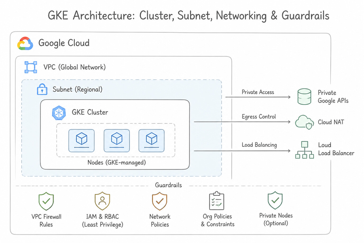
Consideration 1.4a: Choosing public or private cluster nodes and node pools
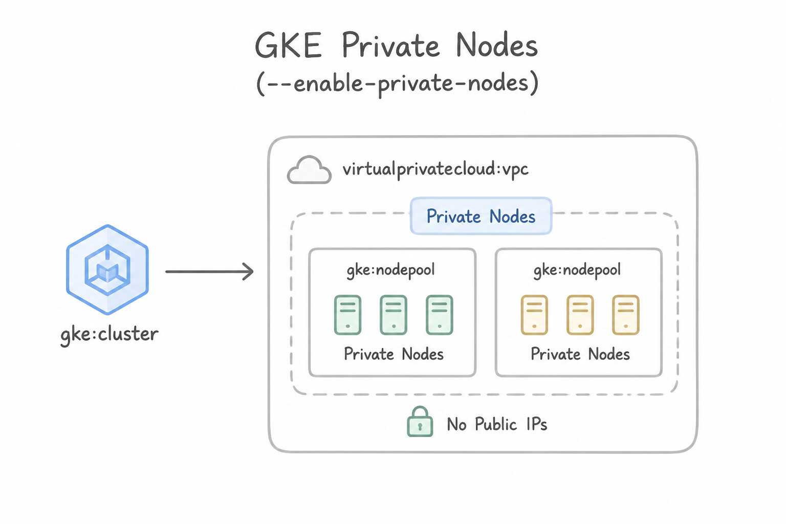
- Private Nodes (
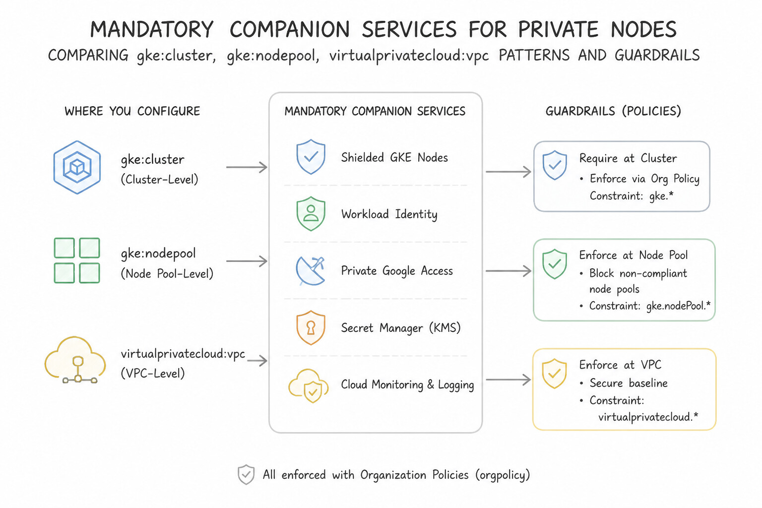
--enable-private-nodes): Worker nodes receive only internal IP addresses from the primary subnet range—zero public IPv4 addresses are attached to node VMs, eliminating direct internet attack surfaces. - Mandatory Companion Services for Private Nodes:
- Private Google Access (
PGA): Automatically enabled (or required on Shared VPC subnets) so private nodes can pull container images from Artifact Registry (pkg.dev) andgcr.ioand write logs/metrics to Google Cloud Observability. - Public Cloud NAT: Required whenever Pods on private nodes need to pull packages from external internet registries (e.g., Docker Hub, GitHub, PyPI) or call third-party public webhooks.
- Per-Node-Pool Override: In GKE Standard, you can even control private vs. public node IP assignment at the individual Node Pool level (
--enable-private-nodes/--no-enable-private-nodes), allowing a cluster to keep 95% of workloads on private node pools while running a specific public-IP node pool (e.g., for UDP game servers requiring direct host ports).
Key Implementation Patterns
- Regulatory Compliance for Financial Workloads: Use Create a private cluster where nodes are configured with internal IP addresses only. Private clusters ensure nodes only receive internal IP addresses, meeting the security requirement. (Avoid alternative: Standard clusters assign public IP addresses to nodes, which violates the requirement even if firewalls block traffic.)
- Internet Egress for Private Nodes: Use Configure Cloud NAT on a Cloud Router for the subnet used by the GKE cluster. Cloud NAT enables outbound internet access for resources without external IP addresses while blocking inbound traffic. (Avoid alternative: Private Google Access is for connecting to Google APIs, not the general internet.)
- Secure Cluster Administration via VPN: Use Create a private cluster. Enable the control plane's private endpoint and disable the public endpoint. Disabling the public endpoint ensures the control plane has no internet exposure, while the private endpoint allows access via VPN.
Key Takeaways (1.4a)
- Standard GKE clusters assign public IP addresses to nodes by default.
- Private clusters ensure nodes only possess internal IP addresses, reducing the attack surface.
- Security compliance (like PCI-DSS) often dictates network isolation levels that require private clusters.
- Modifying managed resources (like GKE nodes) manually is an anti-pattern; use declarative configuration instead.
Consideration 1.4b: Choosing public or private control plane endpoints
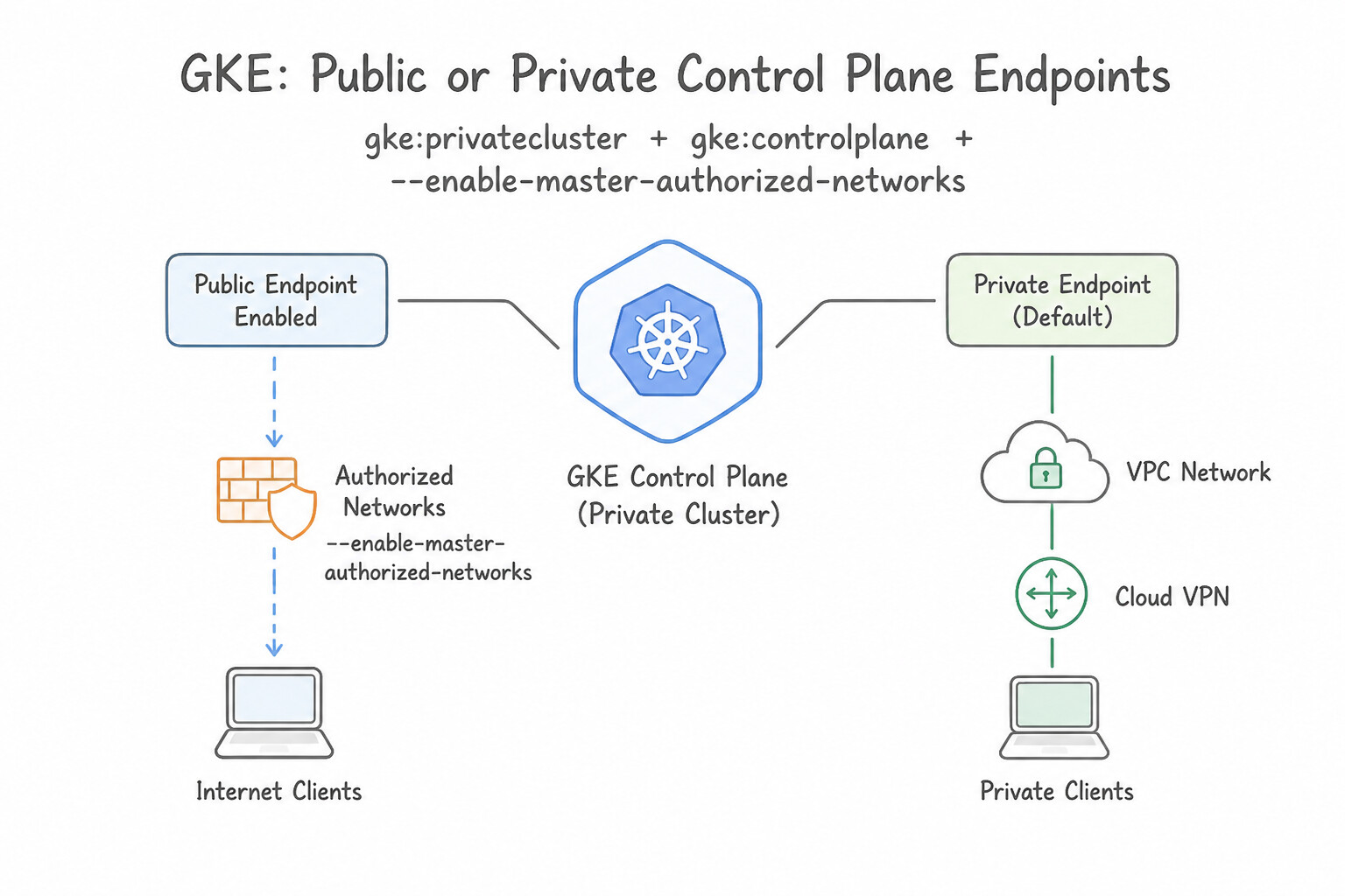
GKE offers two architectural models for reaching the Google-managed kube-apiserver control plane:
- DNS-Based Control Plane Endpoint (
--enable-dns-access— Modern Recommended Standard): - Assigns a unique FQDN (
gke-xxx.us-central1.gke.goog) backed by Private Service Connect (PSC) and Google's API frontend. - Reachable from any VPC (via Private Google Access or PSC endpoints for Google APIs) and from on-premises networks without requiring VPC Network Peering or managing
/28control plane CIDRs! Governed by IAM and optional Authorized Networks. - IP-Based Control Plane Endpoints (Private
/28+ Optional Public IP): - Public Endpoint Enabled + Authorized Networks (
--enable-master-authorized-networks): Exposes an external IP that blocks all internet traffic except explicitly allowlisted corporate/CI-CD CIDRs (plus Google Cloud internal IPs if configured). - Private Endpoint Only (
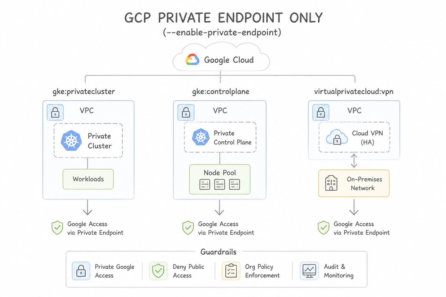
--enable-private-endpoint): Disables external access completely;kubectlmust run inside the VPC or across HA VPN / Cloud Interconnect. - Control Plane Global Access (
--enable-master-global-access): By default, a private control plane endpoint is only reachable from the same region as the cluster! Always enable Control Plane Global Access so management VMs or VPNs/Interconnects in other GCP regions can reach the private/28control plane endpoint.
Key Implementation Patterns
- Strict Financial Compliance Architecture: Use Create a private cluster. Disable access to the public endpoint and enable access to the private endpoint. Disabling the public endpoint ensures the control plane has no public IP, meeting the strict security requirement. (Avoid alternative: Enabling the public endpoint assigns a public IP address to the control plane, which violates the strict security policy.)
- Remote Developer Access via Public Internet: Use Enable the control plane public endpoint. Configure master authorized networks to allow only the developers' static IP addresses. A public endpoint allows internet access, and master authorized networks secure it by allowlisting specific source IP addresses.
- Hybrid Cloud Connectivity Routing: Use Update the Cloud Router to advertise the address range of the control plane as a custom route. Cloud Router does not advertise peered networks by default; you must manually add the GKE control plane range to the BGP advertisements.
Key Takeaways (1.4b)
- GKE Private Clusters ensure worker nodes only have internal IP addresses.
- The GKE Control Plane can have a public endpoint, a private endpoint, or both.
- To strictly prohibit internet access to the control plane, you must explicitly disable the public endpoint.
- Accessing a private-endpoint-only cluster requires a VM in the same VPC, or a connection via Cloud VPN or Cloud Interconnect.
Consideration 1.4c: Planning primary and secondary subnet ranges
- Primary vs. Secondary Ranges:
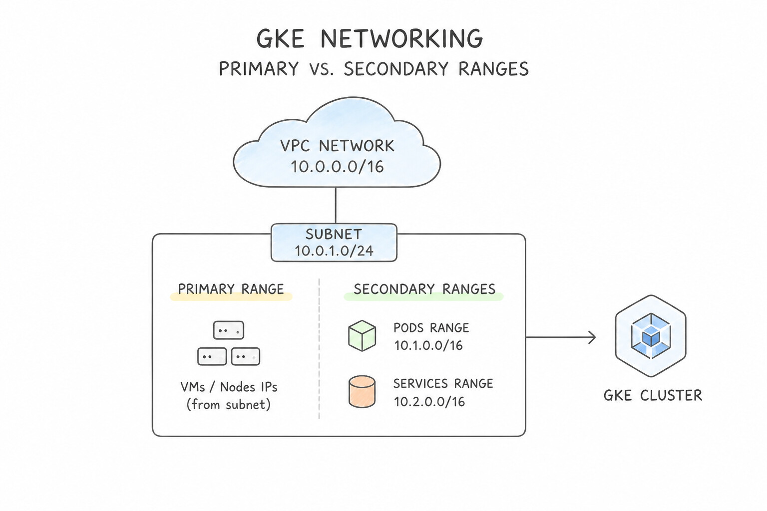
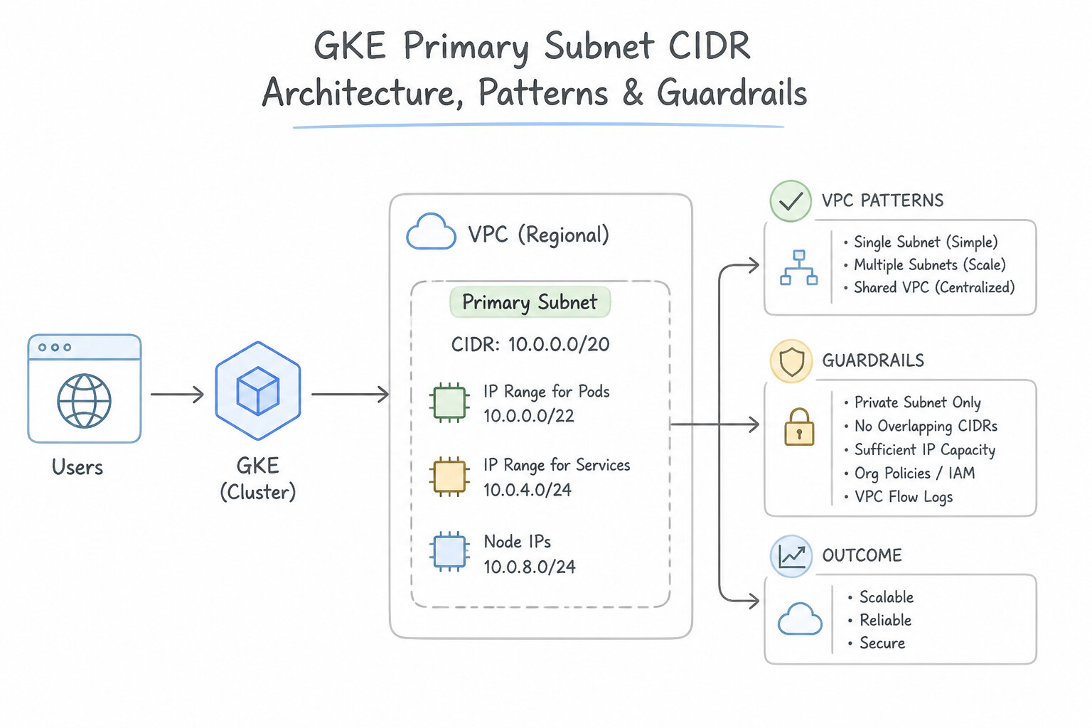
- Primary Subnet CIDR: Used for GKE worker node VM primary internal IPs (
nic0). Can be expanded dynamically with zero downtime (gcloud compute networks subnets expand-ip-range). - Secondary Subnet CIDR (Pods): Used for VPC-native Alias IPs assigned to Pods. Cannot be expanded in place after creation! (Maximum of 30 secondary ranges per VPC subnet).
- Secondary Subnet CIDR (Services): Used for
ClusterIPvirtual IPs inside the cluster. SinceClusterIPs are only significant inside the cluster (iptables/eBPF), GKE can automatically manage the Services range from a non-routable block (34.118.224.0/20) so you don't waste VPC secondary ranges! - Exact Node-to-Pod CIDR Sizing Table (Memorize in Production!):
Max Pods per Node ( --max-pods-per-node) | Reserved IPs per Node ($2 \times \text{Max Pods}$) | Subnet Mask Allocated per Node | Max Nodes Supported in a /21 Pod Range ($2,048$ IPs) |
|---|---|---|---|
8 | $16$ IPs | /28 | 128 nodes |
16 | $32$ IPs | /27 | 64 nodes |
32 | $64$ IPs | /26 | 32 nodes |
64 | $128$ IPs | /25 | 16 nodes |
65–110 (Default 110) | $256$ IPs | /24 | 8 nodes |
111–256 | $512$ IPs | /23 | 4 nodes |
Key Implementation Patterns
- Sizing Primary Ranges for Node Upgrades: Use Configure a /24 subnet range for the nodes. A /24 range offers 252 usable IPs, which covers the 200 IPs needed during the blue-green upgrade. (Avoid alternative: A /26 range offers only 60 usable IPs, which cannot support the 100 baseline nodes.)
- Optimizing IP Consumption with Max Pods Per Node: Use Configure the cluster with a maximum of 16 Pods per node. Reducing max pods per node forces GKE to assign smaller CIDR blocks (/27) to each node, saving IP space. (Avoid alternative: Expanding the range bypasses the constraint but does not optimize the node allocation efficiency.)
- Planning Secondary Ranges for Multiple Clusters: Use Define distinct secondary IP address ranges on subnet-a for the Pods and Services of each cluster. Each cluster in a shared subnet requires unique secondary ranges for Pods and Services to avoid conflicts. (Avoid alternative: Sharing secondary ranges causes IP address conflicts between clusters.)
Key Takeaways (1.4c)
- The primary subnet range in GKE is used for Node IP addresses.
- Always account for 4 reserved IP addresses in every Google Cloud subnet.
- Upgrade strategies like Blue-Green or Surge upgrades require extra IP capacity temporarily (often doubling the node count).
- Calculate the usable IPs: 2^(32-CIDR) - 4.
Consideration 1.4d: Selecting RFC1918, non-RFC1918, or PUPI addresses

When enterprise RFC 1918 (10.0.0.0/8, 172.16.0.0/12, 192.168.0.0/16) space is scarce:
- Keep Node IPs in
RFC 1918, Move Pod & Service IPs to Non-RFC 1918 or PUPI: - Assign a small
RFC 1918primary subnet for Nodes (and internal Load Balancers), and use100.64.0.0/10(Carrier-Grade NAT / RFC 6598),240.0.0.0/4(Class E), or Privately Used Public IPs (PUPI) for the huge Pod secondary range! - Use the GKE-managed Services range (
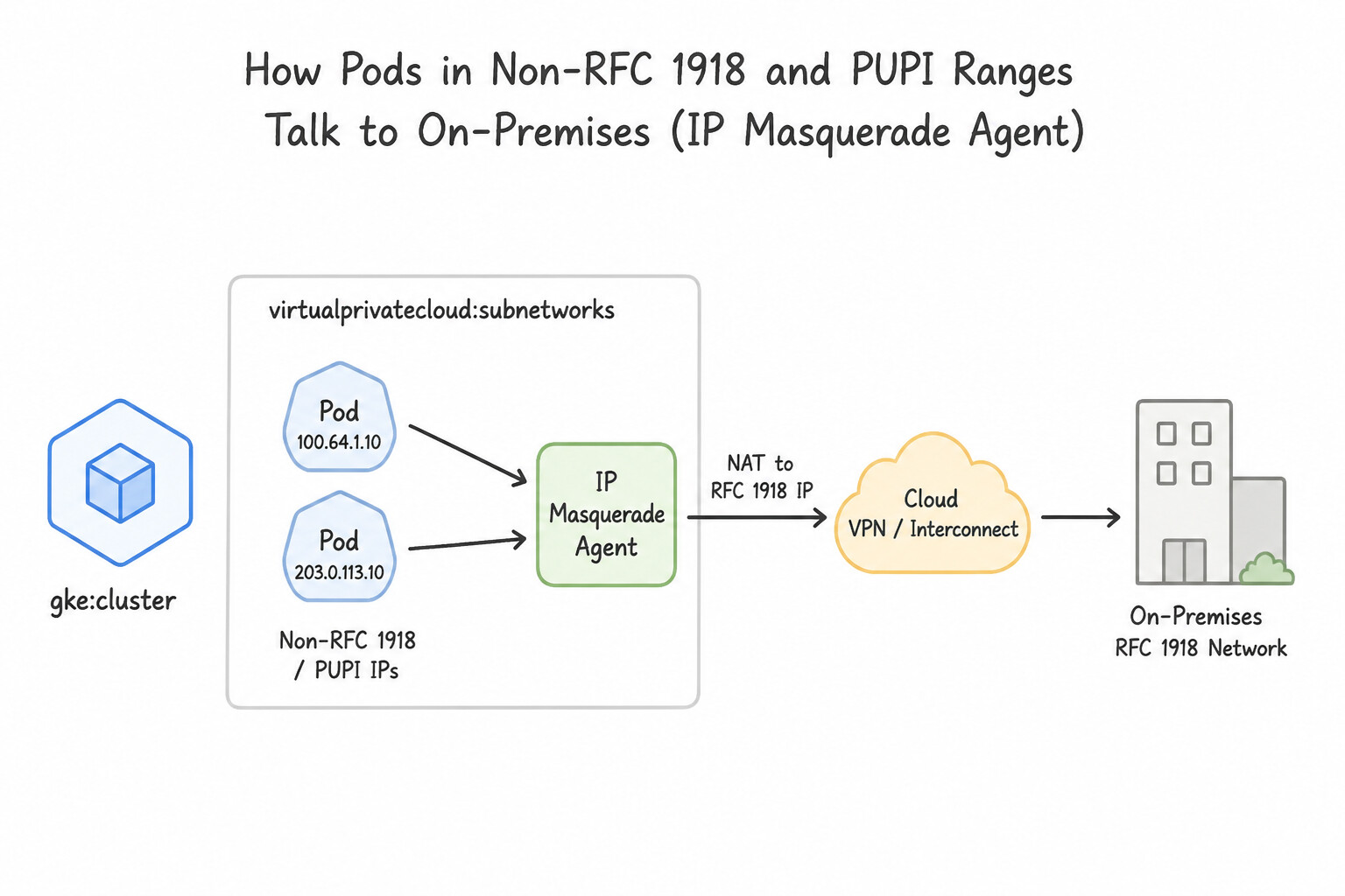
34.118.224.0/20) so Services consume zeroRFC 1918space. - How Pods in Non-RFC 1918 / PUPI Ranges Talk to On-Premises (
IP Masquerade Agent): - Because on-premises routers do not route
240.0.0.0/4or overlapping100.64.0.0/10Pod CIDRs back to each cluster, configureip-masq-agent(nonMasqueradeCIDRs) so egress traffic from Pods to on-premises destinations is SNATed (masqueraded) to the Node's routableRFC 1918primary IP! - Modern GKE Control Plane via
PSC: Modern GKE clusters connect the Google-managed control plane to your VPC using Private Service Connect (PSC) rather than legacy VPC Network Peering—meaning you no longer burn one of your 25 VPC Peering slots per cluster or need to allocate a/28peering subnet!
Key Implementation Patterns
- RFC1918 Exhaustion and CG-NAT Usage: Use Configure the Pod address range using a CIDR block from the 100.64.0.0/10 range. The 100.64.0.0/10 range (RFC 6598) is a valid non-RFC1918 private range supported by GKE when standard private IPs are exhausted. (Avoid alternative: The 224.0.0.0/4 range is reserved for multicast and cannot be used for assigning unicast IP addresses to Pods.)
- Class E Address Space Utilization: Use Configure the IP Masquerade Agent in the cluster to masquerade Pod traffic destined for the on-premises network. Physical hardware often drops Class E traffic; IP masquerading hides the Class E Pod IP behind the Node's RFC1918 IP. (Avoid alternative: Cloud NAT is generally for internet egress; the IP Masquerade Agent is the native GKE solution for internal/hybrid SNAT.)
Key Takeaways (1.4d)
- RFC1918 ranges (10.0.0.0/8, 172.16.0.0/12, 192.168.0.0/16) are the standard for private networks but can be exhausted.
- The 100.64.0.0/10 range (RFC 6598) is a valid alternative for private addressing in Google Cloud.
- Avoid reusing IP ranges to prevent routing conflicts in hybrid networks.
- Multicast (224.0.0.0/4) and Link-Local (169.254.0.0/16) ranges are invalid for Pod IP assignment.
Consideration 1.4e: Planning for IPv6
- Dual-Stack (
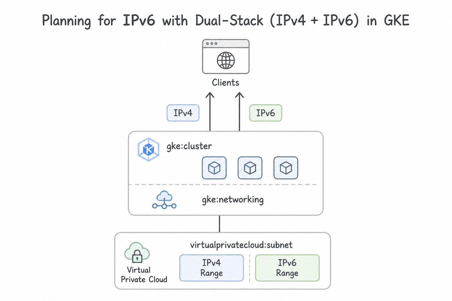
IPv4/IPv6) Architecture: - Enable Dual-Stack IPv6 (
INTERNALULA/64orEXTERNALGUA/64) on the VPC and subnet before creating the GKE Dual-Stack cluster (--stack-type=IPV4_IPV6). - Unlike IPv4 where Pods use a separate secondary subnet range, GKE Dual-Stack IPv6 allocates both Node IPv6 addresses and Pod IPv6 ranges (
/112per node) directly from the subnet's single/64IPv6 range! - Dual-stack Services can be configured as
SingleStack(IPv4orIPv6) orDualStack(PreferDualStack/RequireDualStack).
Key Implementation Patterns
- Dual-stack Subnet Prerequisites: Use Create the subnet with stack-type set to IPV4_IPV6. Select the IPv6 access type as either Internal or External. GKE dual-stack clusters require a dual-stack subnet configured with
stack-type: IPV4_IPV6and a specified access type. (Avoid alternative: A single-stack IPv4 subnet cannot support a dual-stack GKE cluster configuration.) - VPC-native Cluster Requirement: Use Create a VPC-native cluster and enable dual-stack networking settings. Dual-stack networking in GKE requires the cluster to be VPC-native. (Avoid alternative: Routes-based clusters do not support dual-stack networking; this feature is only available on VPC-native clusters.)
- Exposing Services via IPv6 Load Balancer: Use Create a Service of type LoadBalancer. Set the ipFamilies field to include IPv6 and the ipFamilyPolicy to PreferDualStack. Setting the Service type to LoadBalancer with 'IPv6' in ipFamilies provisions an external IPv6 address.
Key Takeaways (1.4e)
- GKE clusters inherit network capabilities from their underlying VPC subnets.
- Dual-stack GKE clusters require a dual-stack subnet (IPv4 and IPv6).
- You cannot enable IPv6 on a cluster if the subnet is IPv4-only.
- Subnets require an IPv6 access type (Internal or External) when dual-stack is enabled.
Consideration 1.4f: Designing load balancing for GKE
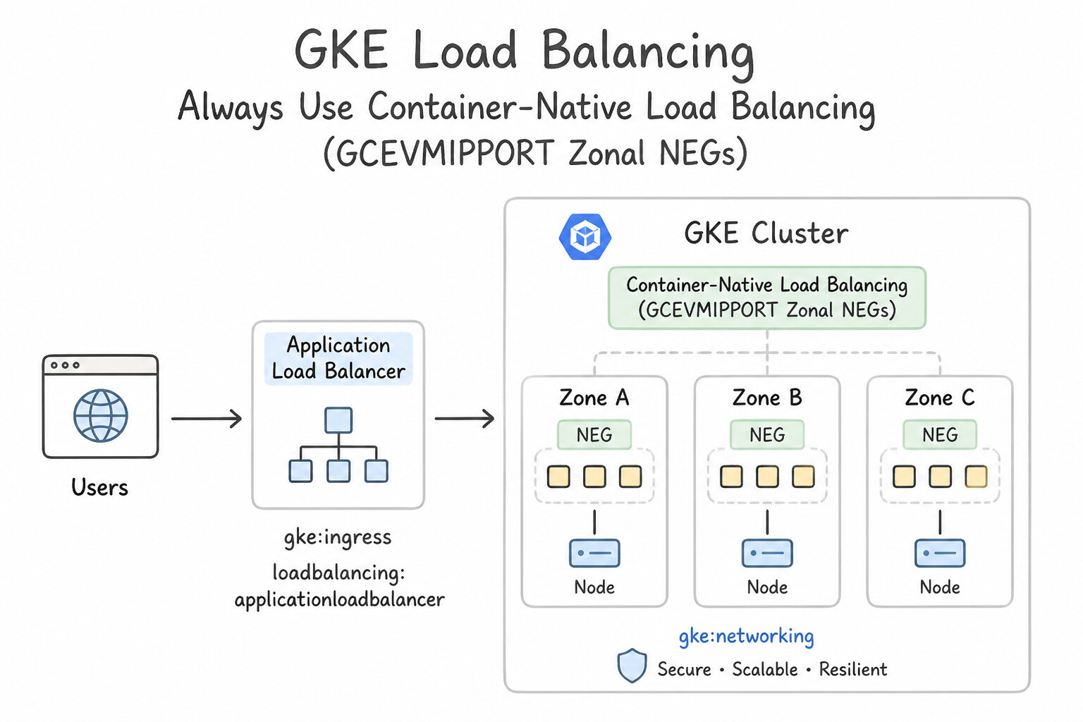
- Always Use Container-Native Load Balancing (
GCE_VM_IP_PORTZonal NEGs): - Enabled by default on VPC-native clusters via the
cloud.google.com/neg: '{"ingress": true}'Service annotation. - Google Cloud Load Balancers send traffic and health check probes directly to individual Pod IP addresses, eliminating the
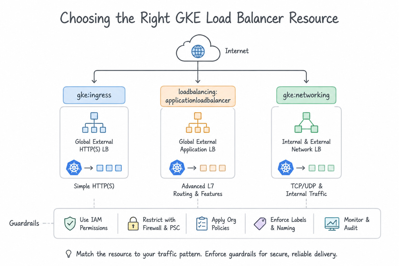
NodePortkube-proxyhop, preserving client context, and ensuring accurate Pod-level health checking. - Choosing the Right GKE Load Balancer Resource:
- GKE Gateway Controller (
Gateway+HTTPRoute): The modern, extensible Kubernetes standard supporting Single-Cluster (gke-l7-global-external-managed,gke-l7-regional-external-managed,gke-l7-rilb) and Multi-Cluster Gateways (gke-l7-gxlb-mc/gke-l7-rilb-mc) with weight-based traffic splitting, header manipulation, and multi-team RBAC separation. - GKE Ingress Controller (
Ingress): Provisions a Classic or Global External Application Load Balancer (networking.gke.io/v1beta1.FrontendConfigandcloud.google.com/v1.BackendConfigattach Cloud Armor, Cloud CDN, IAP, and custom health checks). Serviceoftype: LoadBalancer: Provisions a Layer 4 External Passthrough Network Load Balancer by default, or a Regional Internal Passthrough Network Load Balancer when annotated withnetworking.gke.io/load-balancer-type: "Internal".
Key Implementation Patterns
- Global HTTP(S) Load Balancing with Ingress: Use Define an Ingress resource that maps URL paths to the backend services. An Ingress resource creates a Layer 7 load balancer that handles path-based routing and exposes a single global IP. (Avoid alternative: Service type LoadBalancer creates Layer 4 load balancers with separate IPs and no path-based routing capabilities.)
- Container-Native Load Balancing (NEGs): Use Add the cloud.google.com/neg: '{"ingress": true}' annotation to the Service. This annotation enables Container-Native Load Balancing, routing traffic directly to Pod IPs. (Avoid alternative: Using NodePort and instance groups creates a double-hop network path, increasing latency.)
- Internal Passthrough Network Load Balancer (L4): Use Create a Service of type LoadBalancer with the annotation networking.gke.io/load-balancer-type: "Internal". The annotation networking.gke.io/load-balancer-type: "Internal" instructs GKE to provision an internal Layer 4 Load Balancer instead of an external one.
Key Takeaways (1.4f)
- Ingress for L7: Use Kubernetes Ingress when you need HTTP/HTTPS routing (Layer 7) features like path-based routing and host-based routing.
- Single Global IP: GKE Ingress creates a Global External Application Load Balancer that serves traffic via a single global Anycast IP.
- Services for L4: Use Service type LoadBalancer for simple TCP/UDP (Layer 4) exposure where path inspection is not required.
- Container-Native Load Balancing bypasses Node proxies and targets Pods directly.
Consideration 1.4g: Adding and managing node pool configuration
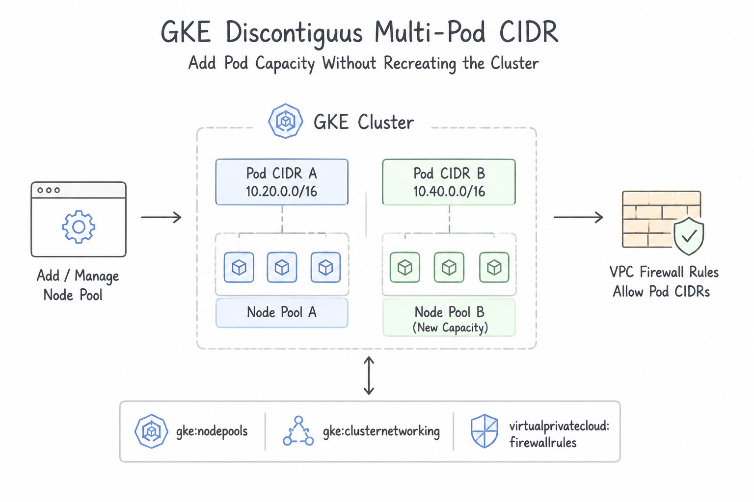
- Discontiguous Multi-Pod CIDR (
Adding Pod Capacity Without Recreating the Cluster): - When a cluster's initial Pod secondary range fills up, you cannot expand that secondary range.
- Instead: (1) Add a new secondary IP range to the VPC subnet (
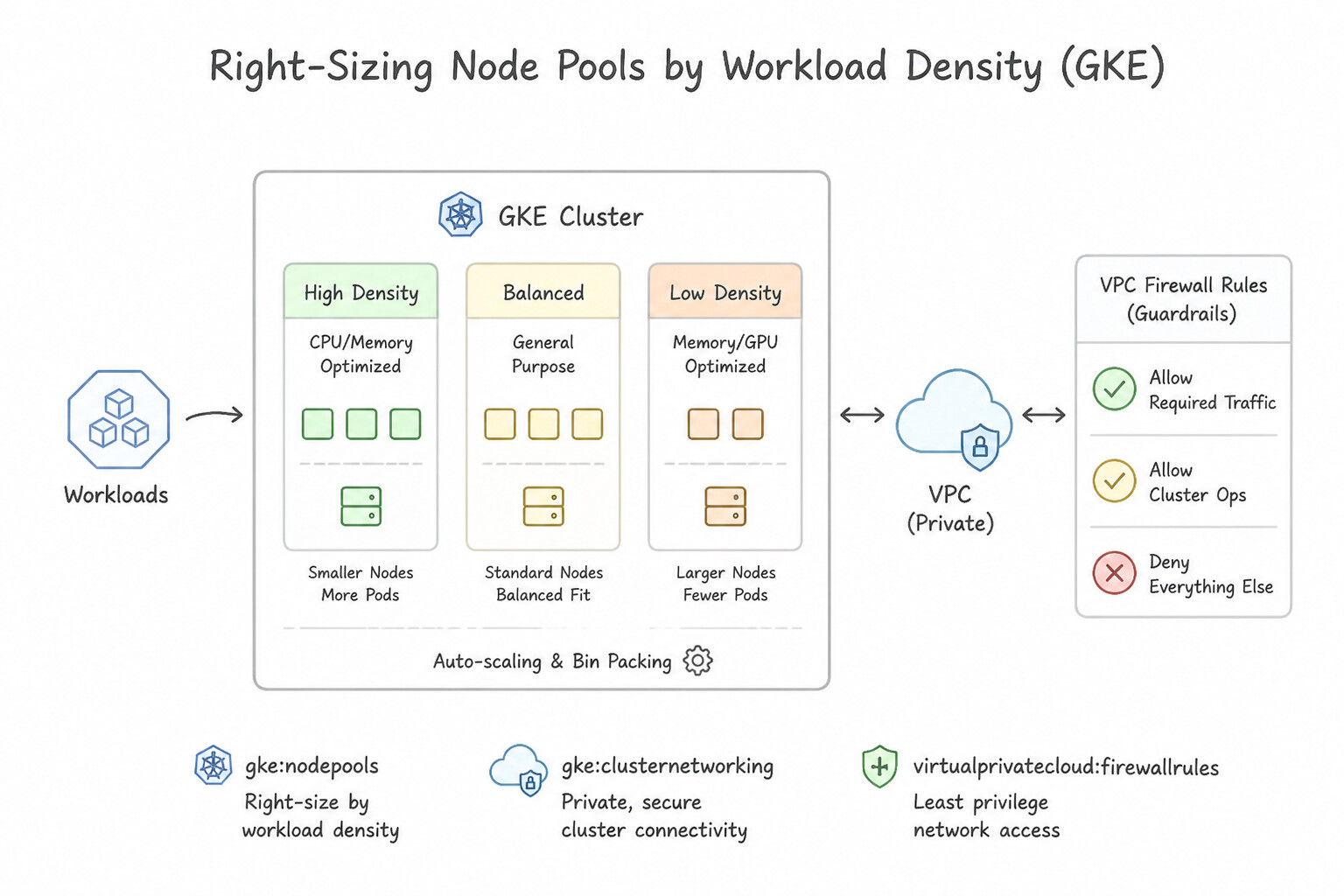
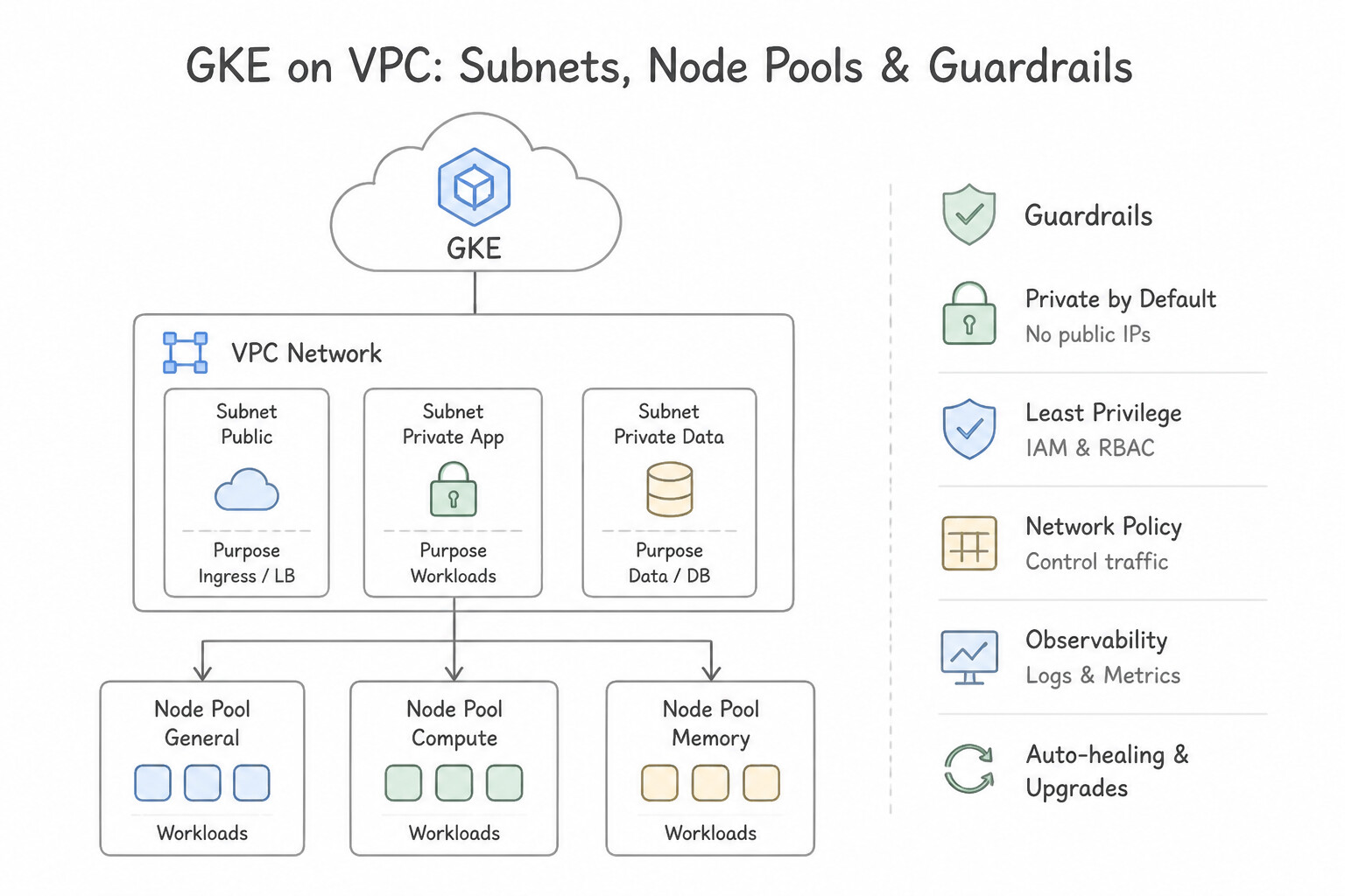
gcloud compute networks subnets update), and (2) create a new Node Pool bound to that new secondary range (--pod-ipv4-range=NEW_RANGE_NAME) or attach--additional-pod-ipv4-rangesto the cluster! - Right-Sizing Node Pools by Workload Density: Create dedicated node pools with tailored
--max-pods-per-nodesettings (e.g., a GPU/ML node pool running only 2 Pods/node sets--max-pods-per-node=8so each GPU node only consumes a/28[16 IPs] instead of wasting a/24[256 IPs]!).
Key Implementation Patterns
- Optimizing IP Address Consumption in High-Density Clusters: Use Set the --max-pods-per-node argument to 32 when creating the node pool. Reducing max-pods-per-node assigns smaller CIDR blocks to nodes, allowing more nodes to fit in the subnet. (Avoid alternative: Default settings allocate a /24 block (256 IPs) per node, which wastes IP addresses if you only run a few Pods.)
- Network Segmentation using Node Pool Tags: Use Run
gcloud container node-pools createwith the--tagsflag. Configure the VPC firewall rule to target the specified tag. Network tags applied to a node pool allow VPC firewall rules to target specifically those VMs. (Avoid alternative: Modifying the default cluster firewall rules affects all nodes, violating the requirement for segmentation.) - Ensuring Availability with Regional Node Pools: Use 12 nodes, because the setting applies per zone and regional pools use three zones by default. Regional pools replicate the per-zone node count across 3 zones (4 nodes 3 zones = 12 nodes). (Avoid alternative: The num-nodes flag defines the count per zone, not the total count for the pool.)*
Key Takeaways (1.4g)
- VPC-native clusters allocate a specific range of IP addresses (CIDR block) to every node for its Pods.
- The size of this CIDR block is determined by the maximum Pods per node setting.
- The default is 110 Pods per node, which results in a /24 block (256 IPs).
- Reducing
--max-pods-per-nodereduces the CIDR block size (e.g., to /26), saving IP addresses and allowing higher node density.
Quick Decision Cheat Sheet (Subsection 1.4)
If the Scenario Requires... | Choose This Google Cloud Pattern | Avoid This Common Mistake |
|---|---|---|
"ML/GPU GKE cluster runs only 2–4 Pods per node and needs to conserve Pod IP space" | Set --max-pods-per-node=8 (allocates a /28 = 16 IPs per node) | Leaving default --max-pods-per-node=110 (wastes a /24 = 256 IPs per node) |
"Eliminate kube-proxy double-hop and allow ALB health checks to probe GKE Pods directly" | Container-Native Load Balancing using GCE_VM_IP_PORT Zonal NEGs | Instance Group ( IG) backends with NodePort services |
"Attach a Cloud Armor WAF security policy or custom timeout to a GKE Ingress" | Create a BackendConfig CRD and reference it on the Kubernetes Service annotation | Modifying FrontendConfig (only handles HTTPS redirects and SSL policies) or VM firewall rules |
"Connect CI/CD runners across multiple non-peered VPCs to a private GKE control plane" | Enable the GKE DNS-Based Control Plane Endpoint ( --enable-dns-access) | Chaining VPC Network Peerings (non-transitive) |
"Expose an internal gRPC or TCP service in GKE to other VMs in the VPC" | Kubernetes Service of type: LoadBalancer with networking.gke.io/load-balancer-type: "Internal" | ClusterIP service (only reachable inside the GKE cluster unless using standalone NEGs) |
Further Reading (Subsection 1.4)
- Private clusters — Provides the definition and architecture details of private clusters in GKE, explaining that nodes in a private cluster only have internal IP addresses.
- Cloud NAT overview — Explains how Cloud NAT enables instances without external IP addresses to access the internet.
- Private clusters — Review the section on 'Access to the cluster master' to understand how public and private endpoints function.
- Control plane security — Discusses authorized networks and how they block untrusted IP addresses from accessing the cluster master.
- Private cluster access from on-premises — Documentation explicitly stating: 'To access the control plane... from on-premises... you must configure the Cloud Router to advertise the control plane's IP address range.'
- IP address planning for GKE — Review the section on 'Cluster sizing' which explains how to size the primary range for nodes.
Subsection 2.4: Configuring and maintaining GKE clusters
The Big Picture
Once a GKE cluster is running in production (Subsection 2.4), day-to-day network operations center on Dataplane enforcement, Source NAT (SNAT) behavior, Pod CIDR expansion, and DNS resolution scaling. In the field, four operational failures occur repeatedly:
- The Default-SNAT Source IP Erasure Trap (2.4f): By default, GKE runs an
ip-masq-agent/ default-SNAT loop that masquerades (SNATs) Pod traffic destined for IP ranges outside the standard RFC 1918 / Pod CIDRs to the worker Node's IP. Conversely, if a Pod uses a10.x.x.xalias IP and talks to an on-premises firewall that only allowlists the GKE Node primary subnet (10.1.0.0/24)—or if the Pod uses a non-RFC 1918 / PUPI range—engineers must either disable default SNAT (--disable-default-snat) so raw Pod Alias IPs are preserved end-to-end, or configure a customip-masq-agentConfigMap (nonMasqueradeCIDRs) to control exactly which destinations trigger SNAT! - The Silent
NetworkPolicyNo-Op Trap (2.4e,2.4g): Applying a KubernetesNetworkPolicyYAML manifest to a GKE Standard cluster does nothing unless a network policy enforcement engine (GKE Dataplane V2 powered by Cilium eBPF, or legacy Calico--enable-network-policy) is enabled on the cluster! - The
kube-dnsConntrack & Latency Bottleneck (2.4k): As a GKE cluster scales past hundreds of nodes or bursts thousands of DNS queries per second ( bolstered byndots:5search path lookups), the centralizedkube-dnsDeployment becomes a CPU andconntrackbottleneck. Production GKE requires enabling NodeLocal DNSCache (a DaemonSet caching DNS responses on every node's loopback IP169.254.20.10over TCP) and/or migrating to Cloud DNS for GKE (which resolves DNS directly at the VPC's local169.254.169.254metadata server with zero in-cluster DNS Pods!).
Consideration 2.4a: Creating VPC-native clusters with alias IPs
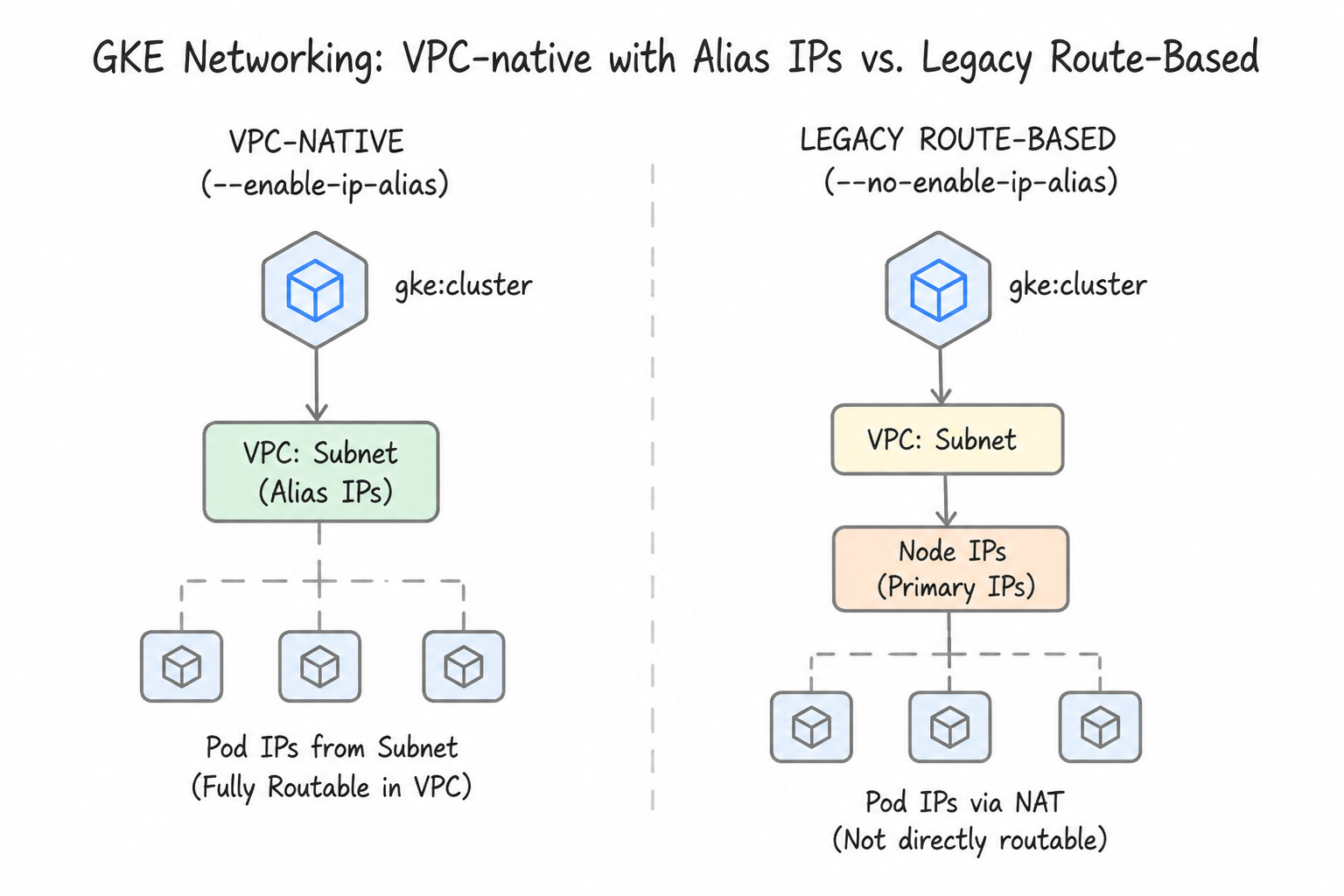
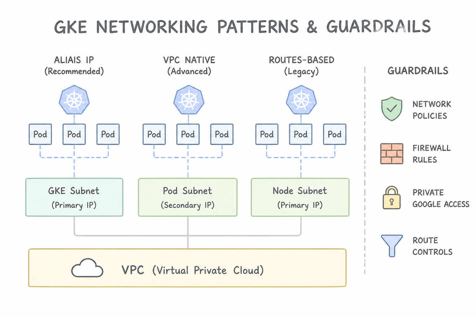
- VPC-Native (
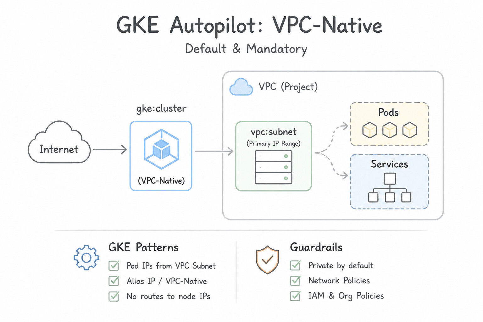
--enable-ip-alias) vs. Legacy Route-Based (--no-enable-ip-alias): - VPC-Native (Default & Mandatory in Autopilot): Allocates Pod IPs from a subnet secondary CIDR range as Google Cloud Alias IP Ranges. The
AndromedaSDN fabric knows where every Pod IP lives natively—no custom static routes are created, Pods are directly reachable across VPC Network Peering, NCC, HA VPN, and Cloud Interconnect, and Container-Native Load Balancing (NEGs) + Private Google Access work out of the box for Pods. - Legacy Route-Based: Creates one custom static route per worker node in the VPC routing table, hitting VPC static route quotas at scale and failing to route across VPC Peering unless custom route export is configured.
Key Implementation Patterns
- Subnet Sizing for VPC-native Clusters: Use Define a secondary range with a /20 CIDR block to accommodate 50 nodes with /26 CIDR blocks. For 30 pods per node, GKE assigns a /26 block (64 IPs) to each node. 50 nodes require 3,200 IPs, fitting into a /20 range. (Avoid alternative: VPC-native clusters allocate fixed CIDR blocks per node, not individual IPs per pod. Summing total pods underestimates the required range.)
- Shared VPC Configuration for GKE: Use Ask the security team to add the secondary IP address ranges to the subnet in the Host Project. Subnets and their secondary ranges must be managed and defined in the Host Project. (Avoid alternative: Service Projects cannot modify subnet configurations defined in the Host Project.)
- Overcoming Route Quotas: Use Create a VPC-native cluster. VPC-native clusters use Alias IPs for Pod routing, eliminating the need for custom static routes per node and bypassing the route quota limit. (Avoid alternative: Custom routes are a VPC-level resource; changing subnets does not bypass the total route quota limit for the network.)
Key Takeaways (2.4a)
- VPC-native GKE clusters allocate Pod IPs using fixed CIDR blocks assigned to each node.
- The size of the per-node block is determined by the max-pods-per-node setting (default is /24).
- Sizing a secondary range requires calculating (Nodes Node Block Size), not (Nodes Pods).
- Reducing max-pods-per-node allows for smaller per-node blocks (/26 or /27), saving IP space.
Consideration 2.4b: Configuring Shared VPC clusters
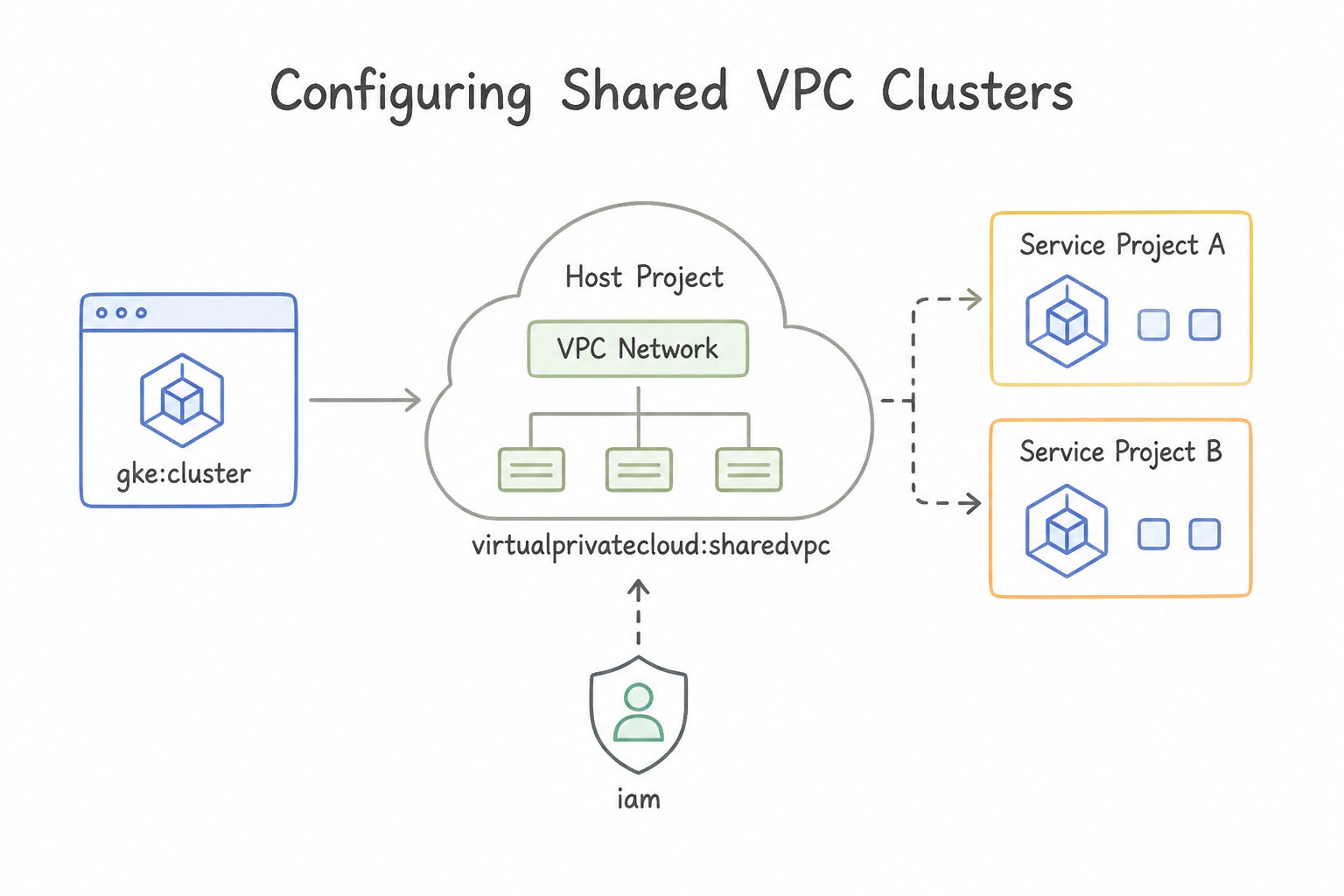
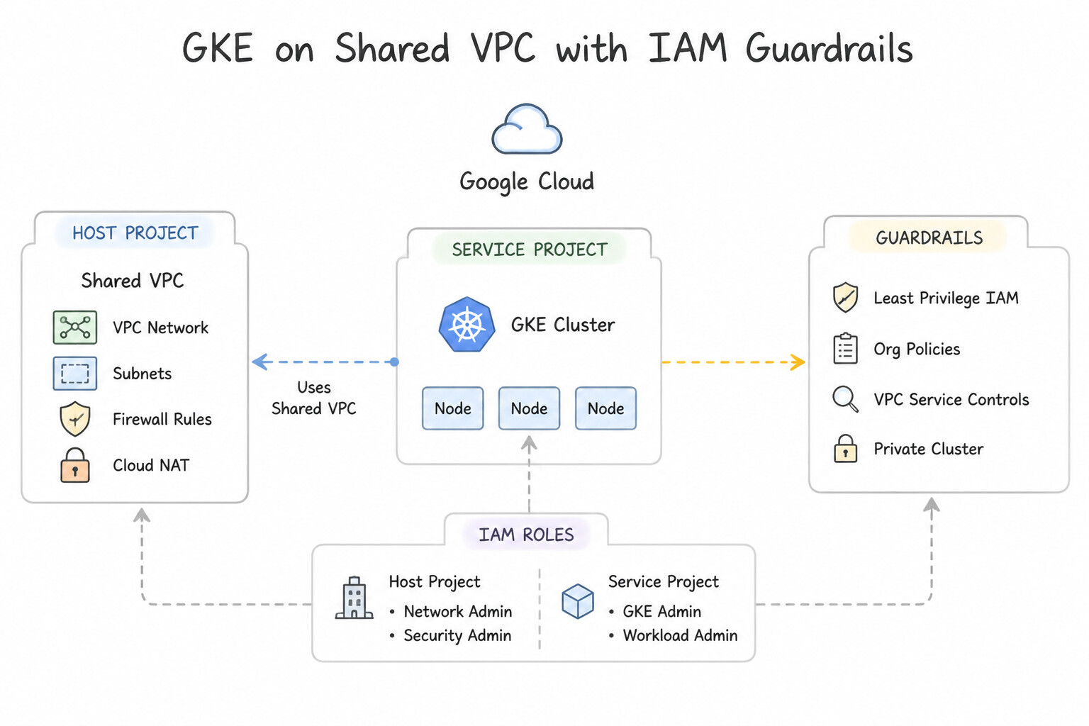
Memorize the exact IAM bindings required in the Shared VPC Host Project before deploying a GKE cluster in a Service Project:
- Service Project GKE Service Agent (
service-SERVICE_PROJECT_NUM@container-engine-robot.iam.gserviceaccount.com): - Grant
roles/compute.networkUseron the specific Host Project Subnet (allowing it to assign Node, Pod, and Service IPs). - Grant
roles/container.hostServiceAgentUser(Kubernetes Engine Host Service Agent User) at the Host Project level (allowing the Service Project's GKE robot to use the Host Project's GKE service agent to manage shared firewall rules and load balancers!). - Service Project Google APIs Service Agent (
SERVICE_PROJECT_NUM@cloudservices.gserviceaccount.com): - Grant
roles/compute.networkUseron the specific Host Project Subnet (so Managed Instance Groups for node pools can provision Compute Engine VMs).
Key Implementation Patterns
- GKE Service Agent Permissions in Host Project: Use In the host project, grant the Kubernetes Engine Host Service Agent User role to the service project's GKE Service Agent. The GKE Service Agent in the service project requires the Kubernetes Engine Host Service Agent User role on the host project to manage shared network resources.
- Subnet Configuration for Pods and Services: Use Add two secondary IP address ranges to the subnet in the Host Project. VPC-native clusters require secondary IP ranges for Pods and Services, which must be configured on the subnet in the Host Project. (Avoid alternative: Service Projects in a Shared VPC setup use subnets shared from the Host Project, not subnets created locally.)
- Firewall Rules for Master-Node Communication: Use Create an ingress firewall rule in the host project. Set the source to the master IP address range and the target to the node tags. Firewall rules for Shared VPCs are managed in the host project, and the master range must be allowed ingress to nodes.
Key Takeaways (2.4b)
- In a Shared VPC setup, network resources belong to the Host Project, while compute resources belong to Service Projects.
- GKE clusters in a Service Project require their Service Agent (robot account) to have permissions in the Host Project.
- The specific role required is
roles/container.hostServiceAgentUserapplied to the Host Project.- Always distinguish between the Default Compute Service Account (used by VMs) and the GKE Service Agent (used by the GKE control plane).
Consideration 2.4c: Configuring private clusters and private control planes
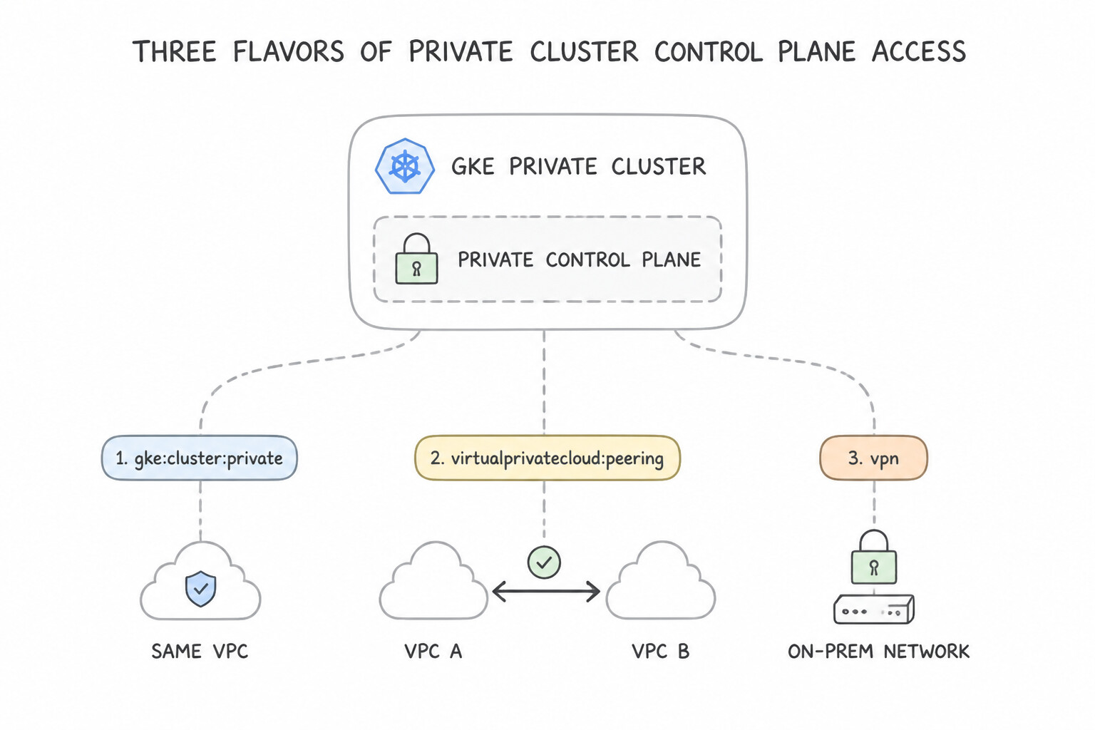
- Three Flavors of Private Cluster Control Plane Access:
- Private Nodes + Public & Private Endpoint + Authorized Networks: External access is restricted to allowlisted CIDRs (
--enable-master-authorized-networks); internal VPC VMs reach the private endpoint. - Private Nodes + Private Endpoint Only (
--enable-private-endpoint): Public control plane access is completely disabled. Management clients (kubectl, Terraform, GitLab/Cloud Build runners) must connect from inside the VPC, a peered VPC, or over HA VPN / Cloud Interconnect (with--enable-master-global-accessenabled if connecting from another region). - Private Nodes + DNS-Based Control Plane Endpoint (
--enable-dns-access): Connects viagke.googFQDN over Private Google Access (199.36.153.8/30/199.36.153.4/30) or PSC from any VPC or hybrid network.
Key Implementation Patterns
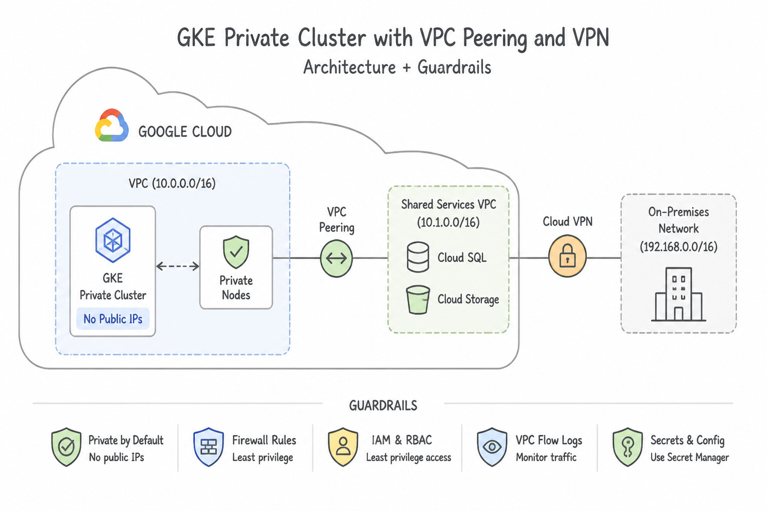
- Enabling On-Premises Access to Private Control Plane: Use Update the VPC Network Peering connection to the GKE cluster master to export custom routes. The GKE master is in a peered VPC network; you must export custom routes (like VPN routes) so the master knows how to route traffic back to on-premises.
- Private Node Internet Access for Updates: Use Configure Cloud NAT for the region and subnet used by the GKE cluster. Cloud NAT enables outbound internet access for private instances without exposing them to inbound traffic. (Avoid alternative: Assigning external IPs defeats the purpose of a private cluster and increases security risks.)
- Securing the Public Endpoint with Authorized Networks: Use Enable master authorized networks on the cluster and add the corporate headquarters' CIDR range to the allowlist. Master authorized networks allow you to restrict access to the control plane public endpoint by IP address range.
Key Takeaways (2.4c)
- Private GKE control planes live in a separate, Google-managed VPC network peered to your VPC network.
- VPC Peering does not exchange custom routes (like those from VPN/Interconnect) by default.
- To allow on-premises access to a peered service (like GKE master), you must enable 'Export custom routes' on the peering connection.
- Connectivity requires both valid network routes (peering config) and security permissions (Authorized Networks).
Consideration 2.4d: Adding authorized networks
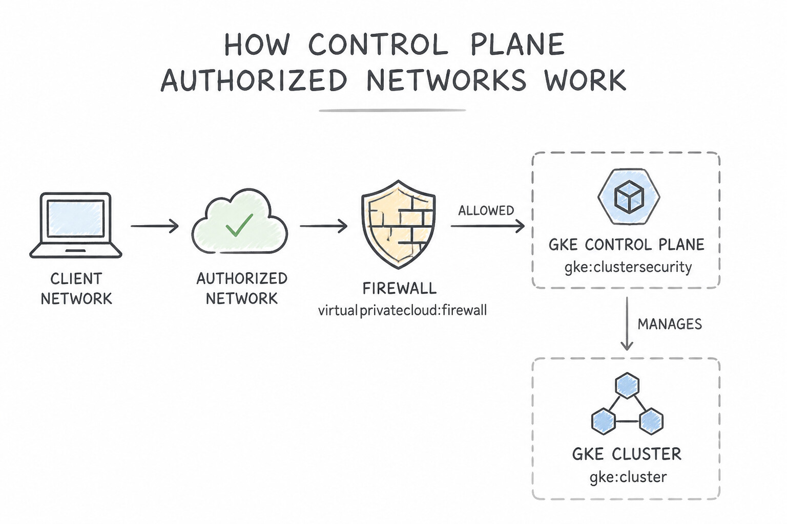
- How Control Plane Authorized Networks Work:
- Acts as an ingress IP allowlist on the GKE
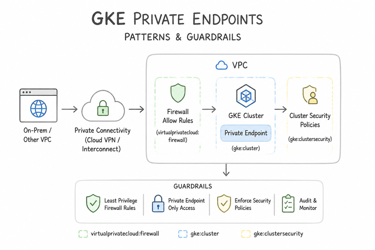
kube-apiserverendpoint (gcloud container clusters update CLUSTER --enable-master-authorized-networks --master-authorized-networks=CIDR1,CIDR2). - Important Nuance for Private Endpoints: When connecting to the private IP endpoint (or DNS-based endpoint) from on-premises over HA VPN / Cloud Interconnect, or from a non-GKE subnet, you must ALSO add the source on-premises / management subnet CIDR to
--master-authorized-networks! Otherwise, the control plane drops packets from any IP outside the cluster's own primary subnet!
Key Implementation Patterns
- Securing Public Master Endpoints: Use Enable master authorized networks and add the corporate office's CIDR range to the allowlist. Master authorized networks restrict access to the public cluster endpoint to specific IP address ranges. (Avoid alternative: VPC firewall rules apply to worker nodes, not the managed GKE control plane endpoint.)
- Updating Authorized Networks Lists: Use Run
gcloud container clusters updatewith the--master-authorized-networksflag specifying a comma-separated list of all existing CIDR ranges plus the new remote office CIDR range. The update command replaces the entire list, so you must include both old and new CIDRs in the request. - Private Cluster Hybrid Connectivity: Use Add the internal IP address (10.10.1.5/32) to the master authorized networks list. Traffic over Cloud VPN preserves the internal source IP address, so the internal IP must be authorized. (Avoid alternative: Public NAT IPs are used for internet traffic, not for traffic routed through a Cloud VPN tunnel.)
Key Takeaways (2.4d)
- VPC Firewall rules protect nodes/VMs inside your VPC, not the GKE managed control plane.
- Master authorized networks allow you to whitelist external IP ranges for access to the GKE public endpoint.
- A Private Cluster can have a public endpoint enabled, disabled, or limited via authorized networks.
- Securing the control plane is a critical step in hardening GKE clusters.
Consideration 2.4e: Enabling Dataplane V2
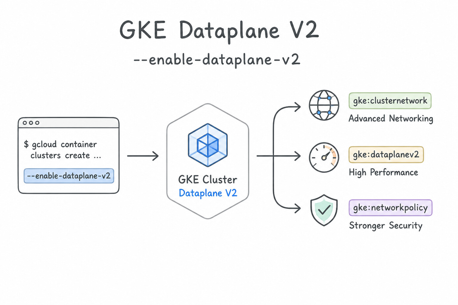
- What GKE Dataplane V2 (
--enable-dataplane-v2) Provides: - Powered by Cilium and Linux kernel eBPF (Extended Berkeley Packet Filter) programs instead of legacy
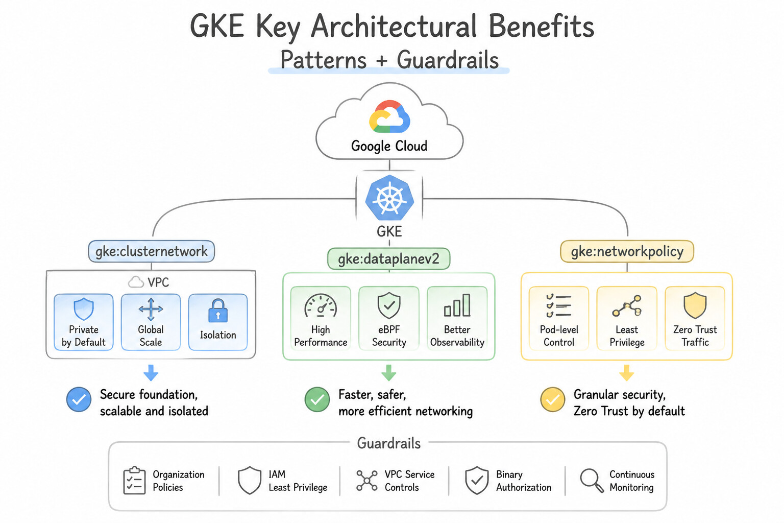
iptableschains (kube-proxyandCalico). - Key Architectural Benefits:
- O(1) Kernel-Level Packet Routing: Eliminates linear
iptablesrule-scanning latency when clusters scale to thousands of KubernetesServices. - Built-In Kubernetes
NetworkPolicyEnforcement: Enforces Pod-to-Pod ingress/egressNetworkPolicymanifests natively out of the box without installing Calico. - Built-In Network Policy Logging & Observability: Streams Pod-level allow/deny verdict logs directly to Cloud Logging (
container.googleapis.com/policy_verdict). - Crucial architectural constraints: GKE Dataplane V2 must be enabled at cluster creation time (
--enable-dataplane-v2on Standard; always enabled on Autopilot). You cannot upgrade an existing non-Dataplane-V2 cluster to Dataplane V2 in place—you must create a new cluster with Dataplane V2 and migrate workloads!
Key Implementation Patterns
- Enabling Dataplane V2 on New Clusters: Use Run gcloud container clusters create with the --enable-dataplane-v2 flag. GKE Dataplane V2 uses eBPF and must be enabled at cluster creation using the --enable-dataplane-v2 flag. (Avoid alternative: The --enable-network-policy flag enables network policy enforcement (often Calico) but does not activate the specific eBPF-based Dataplane V2 architecture.)
- Network Policy Logging for Security Audits: Use Create a NetworkLogging object named default and set the deny logging specification to true. Dataplane V2 uses the NetworkLogging CRD to configure logging for allowed or denied connections by NetworkPolicies. (Avoid alternative: VPC Flow Logs operate at the subnet level and do not provide granular visibility into Kubernetes NetworkPolicy decisions.)
Key Takeaways (2.4e)
- GKE Dataplane V2 uses eBPF for high-performance networking and replaces kube-proxy.
- Dataplane V2 must be enabled at cluster creation and cannot be added later.
- Dataplane V2 includes built-in network policy enforcement without requiring third-party plugins like Calico.
- Dataplane V2 uses eBPF for networking and security in GKE.
Consideration 2.4f: Configuring SNAT and IP masquerade
Understand the two directions of Pod IP translation in GKE:
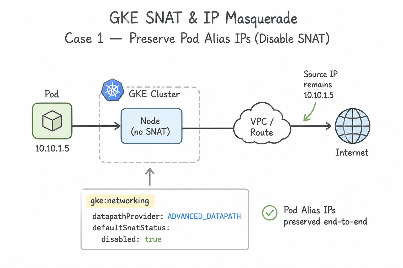
- Case 1 — You Want to PRESERVE Pod Alias IPs (Disable SNAT):
- By default, GKE SNATs Pod traffic destined for non-RFC 1918 IPs (or PUPI ranges) to the worker Node's IP.
- If you route traffic from Pods to Privately Used Public IPs (
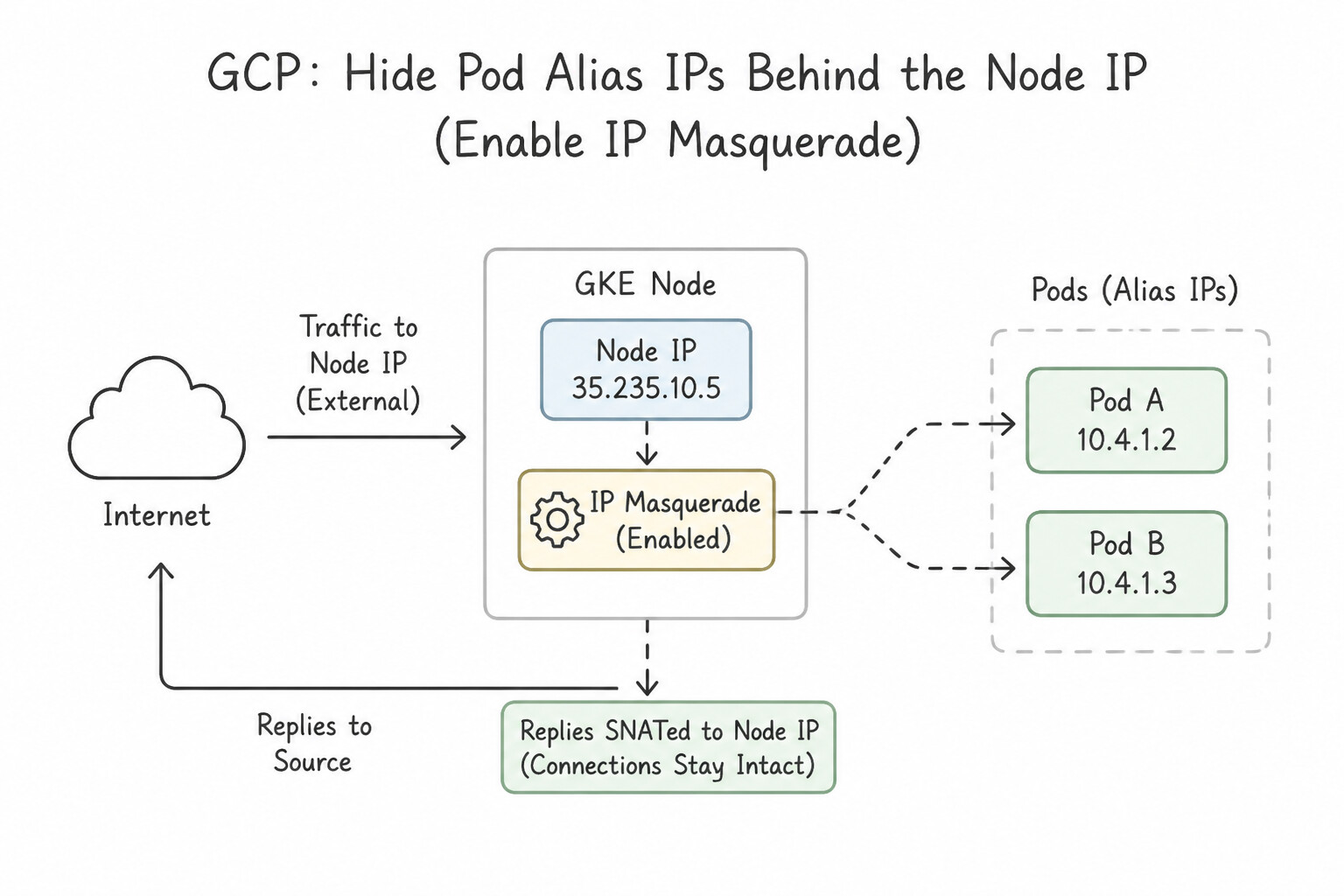
PUPI) or custom ranges over VPN/Interconnect and need the destination firewall to see the original Pod Alias IP, pass--disable-default-snaton the cluster (and use Cloud NAT configured to NAT both primary and secondary subnet ranges for public internet egress). - Case 2 — You Want to HIDE Pod Alias IPs Behind the Node IP (Enable IP Masquerade):
- If your Pods use non-routable CIDRs (
240.0.0.0/4,100.64.0.0/10) or your on-premises firewall only permits the Node primary subnet CIDR (10.1.0.0/24), deploy/update theip-masq-agentConfigMap inkube-systemand remove the on-premises CIDR fromnonMasqueradeCIDRsso traffic to on-premises is SNATed to the Node's primary IP!
Key Implementation Patterns
- Preserving Pod IPs over Cloud VPN: Use Create a ConfigMap for the ip-masq-agent and add the on-premises destination CIDR to the nonMasqueradeCIDRs list. The ip-masq-agent controls SNAT behavior; adding the destination to nonMasqueradeCIDRs prevents the Pod IP from being hidden behind the Node IP.
- Forcing SNAT for Unroutable Peered Networks: Use Edit the
ip-masq-agentConfigMap and ensure the partner's CIDR range is NOT included in thenonMasqueradeCIDRslist. Excluding the range fromnonMasqueradeCIDRsforces the agent to masquerade traffic using the Node IP. - Handling Link-Local Traffic: Use Set the masqLinkLocal parameter to true in the ip-masq-agent ConfigMap. Setting masqLinkLocal to true overrides the default behavior and forces the agent to masquerade traffic destined for the 169.254.0.0/16 range. (Avoid alternative: Adding the range to nonMasqueradeCIDRs prevents SNAT, preserving the Pod IP address instead of using the node IP address.)
Key Takeaways (2.4f)
- GKE clusters perform IP masquerading (SNAT) for egress traffic by default to ensure routability.
- The ip-masq-agent is used to configure which destination ranges should bypass this masquerading.
- The
nonMasqueradeCIDRslist in the ip-masq-agent ConfigMap defines destinations where Pod IPs should be preserved.- Preserving Pod IPs is essential for proper firewalling and logging when connecting to on-premises networks via Cloud VPN or Interconnect.
Consideration 2.4g: Creating network policies
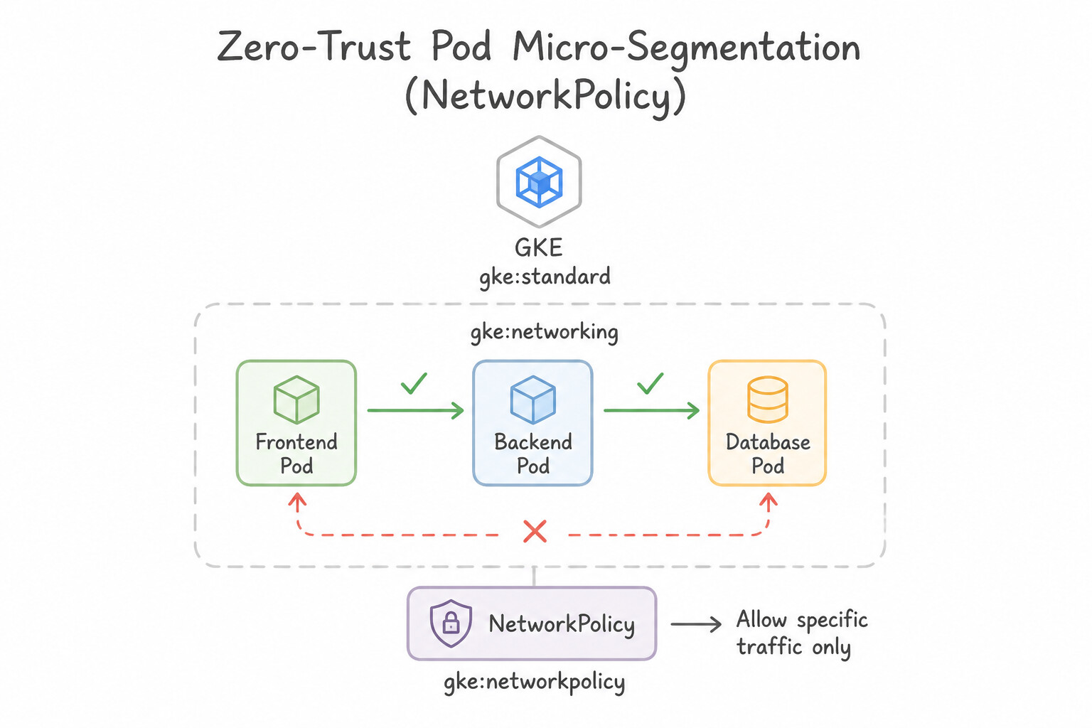
- Zero-Trust Pod Micro-Segmentation (
NetworkPolicy): - By default in Kubernetes, all Pods in a cluster can communicate with all other Pods across all Namespaces without restriction.
- Creating a
NetworkPolicytargeting a group of Pods (podSelector) immediately places those Pods in default-deny mode for the specifiedpolicyTypes(Ingressand/orEgress), allowing only traffic matching theingress/egressfrom/toselectors (podSelector,namespaceSelector, oripBlock). - Common common pitfalls (
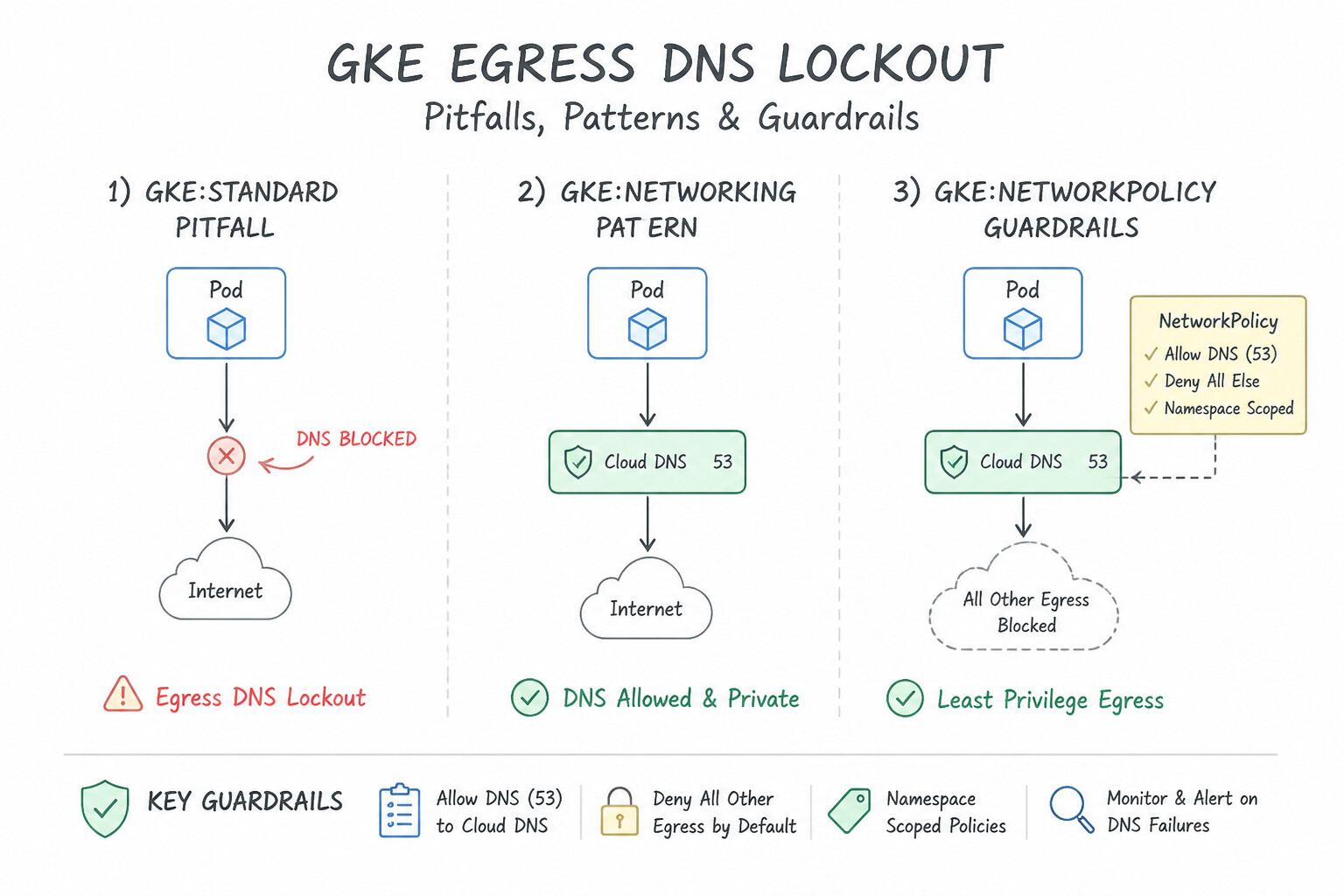
Egress DNS Lockout): When you apply a default-deny EgressNetworkPolicy(policyTypes: ["Egress"]) to a namespace, Pods will immediately fail to resolve DNS names unless you explicitly add an egress rule allowingUDPandTCPport53tokube-dns/NodeLocal DNSCache/169.254.169.254!
Key Implementation Patterns
- Enabling Network Policy Enforcement: Use Enable the network policy enforcement feature on the GKE cluster. Network policies in GKE Standard require the network policy addon to be explicitly enabled on the cluster. (Avoid alternative: Kubernetes NetworkPolicies do not use priority fields; enforcement depends on the cluster configuration.)
- Implementing Default Deny-All: Use Create a NetworkPolicy in the namespace with an empty podSelector and include Ingress in policyTypes without listing any rules. An empty podSelector selects all pods, and defining Ingress type without rules denies all incoming traffic by default.
- Restricting Ingress by Label: Use Define a NetworkPolicy that targets the 'backend' pods. In the 'ingress' section, add a 'from' rule using 'podSelector' and 'matchLabels' to identify the 'frontend' pods. Using 'podSelector' allows you to dynamically allow traffic based on pod labels, which is the standard method for microsegmentation in Kubernetes.
Key Takeaways (2.4g)
- Network Policies in GKE Standard are not active by default.
- You must enable the network-policy addon or use Dataplane V2 for enforcement.
- Kubernetes manifests can be applied successfully even if the enforcing controller is missing.
- NetworkPolicies are namespaced resources used for pod-level segmentation.
Consideration 2.4h: Configuring Pod and service ranges
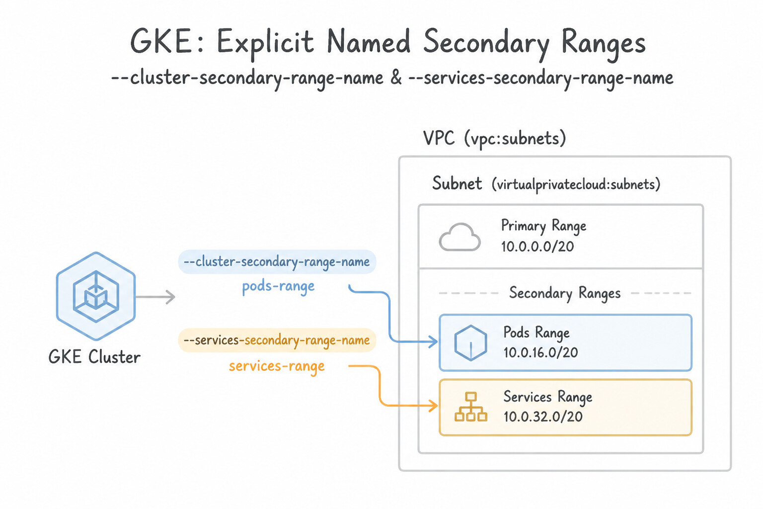
- Explicit Named Secondary Ranges (
--cluster-secondary-range-name&--services-secondary-range-name): - In a Shared VPC, the Network Admin pre-creates named secondary IP ranges on the Host Project subnet (
pods-range-1,services-range-1), and the Service Project admin references those exact names when creating the cluster. - Never share the same Pod secondary range or Service secondary range between two different GKE clusters at the same time (causes IP collisions)—except you can omit
--services-secondary-range-nameon modern clusters to use GKE-managed cluster-local Service IPs (34.118.224.0/20).
Key Implementation Patterns
- Initial Pod Address Range Sizing: Use Select a /18 range (16,384 IP addresses). A /18 range provides enough IP space for 50 nodes, where each node consumes a /24 block. (Avoid alternative: A /21 range is insufficient for the required number of nodes and pods.)
- Optimizing IP Consumption with Max-Pods: Use Set default-max-pods-per-node to 16 when you create the cluster. Lowering the max-pods setting reduces the size of the CIDR block assigned to each node, saving IP addresses. (Avoid alternative: The default value of 110 assigns a large /24 block to each node, which wastes IPs in this scenario.)
- Shared VPC Range Management: Use Request the Shared VPC Admin to add the secondary IP address ranges to the shared subnet in the host project. Subnets and their secondary ranges are managed in the Host Project; the Service Project Admin must request the Host Admin to create them.
Key Takeaways (2.4h)
- VPC-native GKE clusters allocate a specific CIDR block to each node for Pod IPs.
- The default allocation is a /24 block per node, assuming 110 pods maximum.
- Cluster sizing calculations must account for the block size per node, not just the raw count of pods.
- Always select a secondary range that accommodates the node count multiplied by the per-node block size.
Consideration 2.4i: Deploying additional Pod ranges
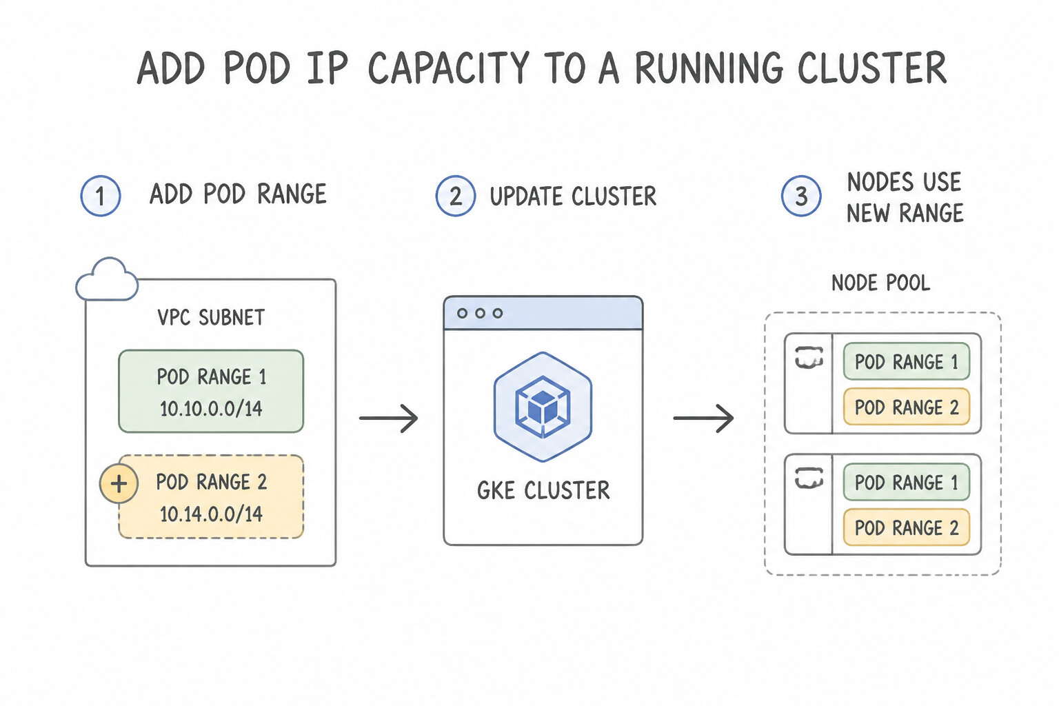
- 3-Step Workflow to Add Pod IP Capacity to a Running Cluster:
- Add a new secondary IPv4 range (
pods-range-2) to the VPC subnet (gcloud compute networks subnets update SUBNET --add-secondary-ranges=pods-range-2=10.200.0.0/18). - Attach the new range to the GKE cluster (
gcloud container clusters update CLUSTER --additional-pod-ipv4-ranges=pods-range-2) OR create a new Node Pool pinned directly to that range (gcloud container node-pools create pool-2 --cluster=CLUSTER --pod-ipv4-range=pods-range-2). - Zero cluster downtime and zero disruption to existing Pods on
pool-1!
Key Implementation Patterns
- Expanding Exhausted Pod IP Space: Use Add a new secondary IP address range to the existing subnet. Use the gcloud container clusters update command with the --additional-pod-ranges flag to assign the new range to the cluster. Add a new secondary range to the subnet and update the cluster to use it as an additional Pod range.
- Dedicated Ranges for New Node Pools: Use Add a new secondary IP address range to the existing subnet. Create the node pool using the --pod-secondary-range-name flag. Add a secondary range to the subnet and assign it to the node pool using the --pod-secondary-range-name flag.
- Peered VPC CIDR Conflicts: Use Inspect the routes advertised by the on-premises network to identify the conflict. Select a different IP address range that does not overlap with the peered network. VPC peering requires globally unique IP ranges across all connected networks; you must choose a non-overlapping range.
Key Takeaways (2.4i)
- VPC-native clusters use secondary subnet ranges for Pods.
- Primary subnet ranges are for Nodes.
- You can add additional Pod IP ranges to an existing cluster to solve IP exhaustion.
- Avoid recreating clusters for capacity issues if seamless updates are available.
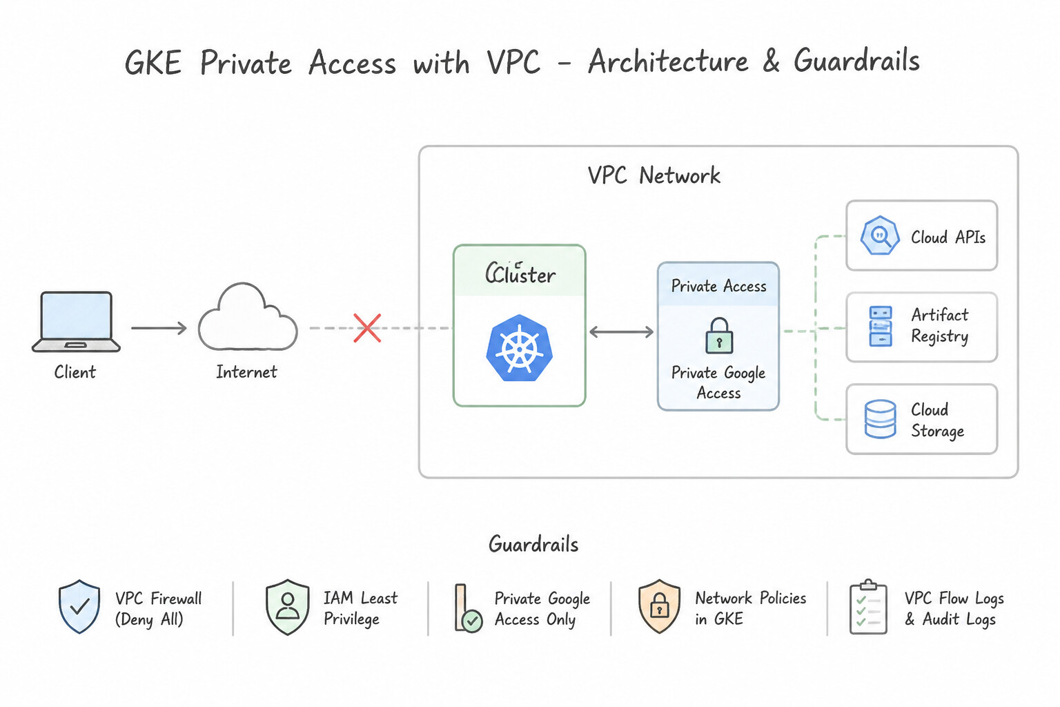
Consideration 2.4j: Using DNS-based endpoint for control plane access
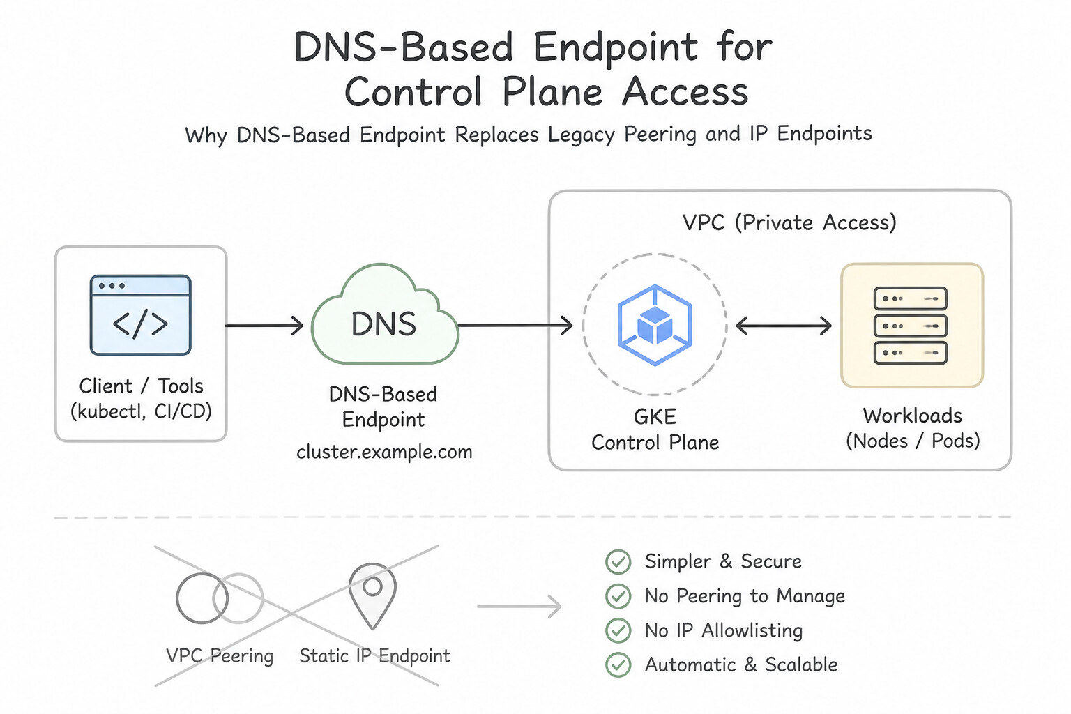
- Why
DNS-Based EndpointReplaces Legacy Peering/IP Endpoints: - Legacy private GKE clusters used VPC Network Peering between the customer VPC and a Google-managed control plane VPC, requiring a non-overlapping
/28CIDR and suffering from VPC Peering non-transitivity. - Enabling DNS-Based Control Plane Access (
--enable-dns-access) exposes the control plane on a globally routable Google API FQDN (*.gke.goog) backed by Private Service Connect (PSC) and Private Google Access (PGA). - Any client in any peered VPC, NCC spoke, or on-premises data center that can reach
private.googleapis.com(199.36.153.8/30) orrestricted.googleapis.com(199.36.153.4/30) can authenticate to the GKE control plane via IAM (and optional Authorized Networks) without managing IP routes or/28subnets!
Key Implementation Patterns
- GKE cluster control plane endpoint setting that restricts management access strictly: Use Private endpoint. A private endpoint assigns an internal IP address to the control plane and disables public internet access. (Avoid alternative: Dual-stack enables both IPv4 and IPv6 communication, not internal isolation of the control plane.)
Key Takeaways (2.4j)
- A Private endpoint assigns an internal IP address to the GKE control plane and blocks all external internet access.
- Authorized networks can restrict public endpoints to specific IP address blocks, but disabling the public endpoint is required to restrict access exclusively to internal IP addresses.
- Private cluster control plane communication relies on VPC Network Peering between the customer VPC network and the Google-managed control plane VPC network.
Consideration 2.4k: Configuring DNS (local DNS cache, Cloud DNS, and kube-dns)
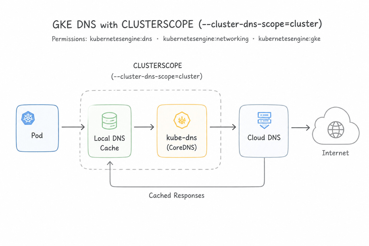
Compare GKE's three DNS architectures:
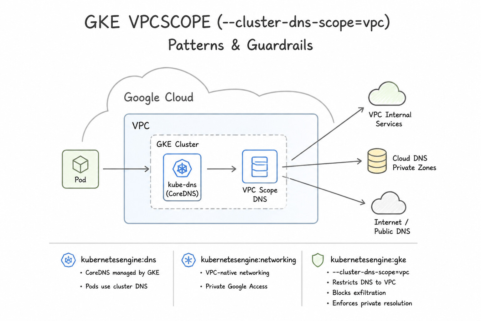
kube-dns(Default in Standard Clusters): Runs as an in-cluster Deployment autoscaled bykube-dns-autoscaler. At high QPS, every Pod lookup traversesiptables/eBPFover UDP tokube-dnsPods, which can exhaust Linuxconntracktables and spike tail latency.NodeLocal DNSCache(--update-addons=NodeLocalDNS=ENABLED): Runs a lightweight caching DNS proxy DaemonSet on every worker node listening on link-local IP169.254.20.10. Pods query their local node cache first, and cache misses are upgraded to TCP towardkube-dnsor Cloud DNS—eliminating UDPconntrackraces and slashing DNS latency.Cloud DNS for GKE(--cluster-dns=clouddns): Replaceskube-dnsPods completely by resolving cluster Services and Pods directly via Google's local VM Metadata Server (169.254.169.254) with zero in-cluster compute overhead! Offered in two scopes:CLUSTER_SCOPE(--cluster-dns-scope=cluster): Cluster DNS names (svc.cluster.local) are only resolvable by Pods inside that cluster.VPC_SCOPE(--cluster-dns-scope=vpc): Automatically publishes GKE headless andClusterIP/ Internal LB service records into a Cloud DNS Private Zone bound to the VPC, allowing Compute Engine VMs, Cloud Run services, and on-premises clients in the VPC to resolve GKE services directly by DNS name!
Key Implementation Patterns
- Managed node-level DNS caching mechanism available in GKE: Use NodeLocal DNSCache. NodeLocal DNSCache deploys a local caching agent on each node to reduce DNS latency and bypass connection tracking. (Avoid alternative: Cloud DNS Peering routes queries between distinct VPC networks rather than caching queries locally on GKE nodes.)
- Natively supported DNS services used for internal cluster name resolution in Google: Use Kube-dns / Cloud DNS. GKE natively integrates kube-dns and Cloud DNS for internal cluster name resolution. (Avoid alternative: BIND9 is not a native DNS service integrated with GKE Dataplane V2.)
Key Takeaways (2.4k)
- NodeLocal DNSCache runs as a DaemonSet on each node to provide localized DNS caching.
- Local caching avoids iptables conntrack race conditions and packet drops.
- DNS lookups achieve lower latency and higher throughput inside GKE clusters.
- GKE supports two native DNS resolution architectures: standard
kube-dnsand managedCloud DNS for GKE.
Quick Decision Cheat Sheet (Subsection 2.4)
If the Scenario Requires... | Choose This Google Cloud Pattern | Avoid This Common Mistake |
|---|---|---|
"Upgrade an existing GKE Standard cluster to Dataplane V2" | Create a new GKE cluster with --enable-dataplane-v2 and migrate workloads via Blue/Green or Multi-Cluster Gateway/DNS | Trying to enable Dataplane V2 in place on an existing cluster (unsupported; flag is creation-time only) |
"Pods lose all DNS resolution immediately after applying an Egress NetworkPolicy" | Add an explicit Egress allow rule for UDP and TCP port 53 in the NetworkPolicy | Disabling Dataplane V2 or restarting kube-dns |
"Preserve original GKE Pod Alias IPs when Pods communicate with Privately Used Public IPs ( PUPI) or external VPCs" | Enable --disable-default-snat on the GKE cluster | Deploying ip-masq-agent to masquerade all traffic |
"Eliminate in-cluster DNS Pod CPU/memory overhead and resolve cluster.local via the VPC Metadata Server" | Cloud DNS for GKE ( --cluster-dns=clouddns) | Scaling kube-dns replicas to 50 |
"Allow kubectl access to a private GKE control plane from any peered VPC or VPC-SC perimeter without /28 peering routes" | DNS-Based Control Plane Endpoint ( --enable-dns-access) | Legacy IP-based private endpoint without Global Access |
Further Reading (Subsection 2.4)
- IP address management strategies - GKE — Refer to the section describing how the Pod address range is assigned to nodes based on the maximum pods per node setting. Specifically, note the table linking max_pods to CIDR mask sizes (e.g., 30 pods uses /26).
- Set up clusters with Shared VPC — Describes the prerequisites and steps for setting up a GKE cluster in a Shared VPC, including the requirement to manage subnets and secondary ranges in the host project.
- VPC-native clusters — Explains the benefits of VPC-native clusters, including the elimination of custom static routes for Pod ranges.
- Routes and quotas — Details the quotas for static routes within a VPC network.
- Setting up clusters with Shared VPC — Refer to the section 'Creating a subnet and two secondary ranges'. It explicitly states that the Host Project admin must create the subnet and secondary ranges for Pods and Services before the Service Project admin can create the cluster.
- GKE Shared VPC Requirements — Documentation detailing the responsibilities in a Shared VPC, specifically mentioning that firewall rules must be managed in the host project.
Book TOC · Previous · Chapter 3 of 8 · Next
AwesomeGCP.com Learning
The approach taken is a question-led learning approach: you explore realistic project scenarios where you need to make decisions or take actions to achieve business goals within specific constraints. Instead of passive learning, you are challenged to think and work through the options to master the Professional Cloud Network Engineer (PCNE) certification!