Book TOC · Previous · Chapter 2 of 8 · Next
Chapter Focus: Subnet expansion, Private Google Access, Private Service Connect (Endpoints, Backends, Service Automation), VPC Peering custom route exchange, Policy-Based Routing, and NCC star/mesh hubs.
Subsection 2.1: Configuring VPCs
The Big Picture
Designing a VPC on a whiteboard (Section 1) is only half the battle; implementing and modifying live VPC resources (Subsection 2.1) is where subtle configuration flags cause production outages. Consider four classic Day-2 pitfalls:
- The One-Sided Peering & Missing Route Export Trap (2.1b): An engineer runs
gcloud compute networks peerings createinProject-AtargetingProject-Band wonders why traffic drops. VPC Network Peering staysINACTIVEuntil both network administrators independently create matching peering configurations—and even whenACTIVE, only local subnet routes are exchanged unless--export-custom-routesand--import-custom-routesare explicitly enabled on matching sides. - The Shared VPC Missing Service Agent IAM Trap (
2.1c,2.1d): A network admin grants a developerroles/compute.networkUseron a Host Project subnet. The developer can create a single standalone VM, but when they try to create a Managed Instance Group (MIG) or GKE Cluster, deployment fails withPermission 'compute.subnetworks.use' denied! Why? Because automated controllers like MIGs and GKE execute using the Service Project's Google APIs Service Agent (PROJECT_NUMBER@cloudservices.gserviceaccount.com) and GKE Service Agent, which also require subnet-levelcompute.networkUserpermissions! - The VPC Service Controls (
VPC-SC) Lockout Trap (2.1g): Wrapping a project in a VPC Service Controls Perimeter in Enforced Mode immediately blocks external CI/CD pipelines, cross-project BigQuery joins, and on-premises users unless the engineer first audits traffic in Dry-Run Mode and configures granular Ingress Rules, Egress Rules, Access Context Manager (ACM) Access Levels, or Perimeter Bridges.
Consideration 2.1a: Creating VPC resources including networks, subnets, firewall rules, PSA subnet, private pools
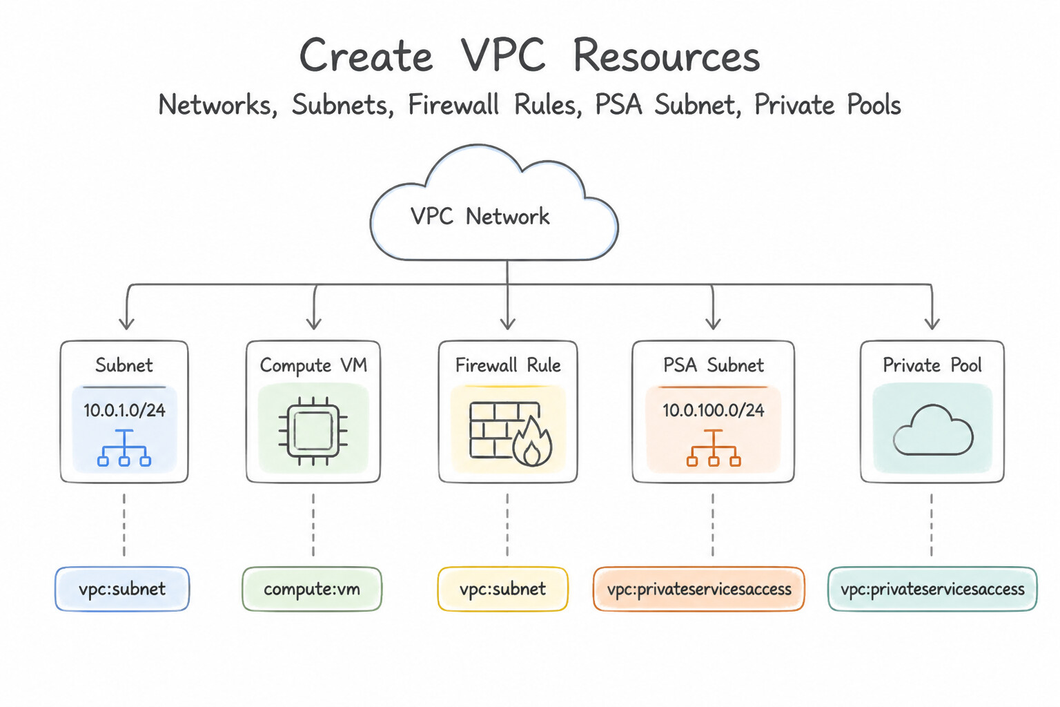
- VPC & Subnet Creation: Always create Custom-Mode VPCs (
--subnet-mode=custom) for production. If a legacy Auto-Mode VPC exists, convert it one-way to Custom Mode (--switch-to-custom-subnet-mode) so you can delete unused regional subnets and prevent10.128.0.0/9CIDR collisions. - Private Services Access (
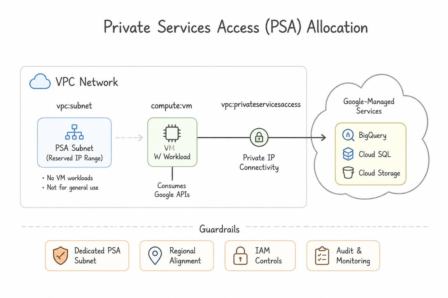
PSA) Allocation: - Reserve an internal IP range with
--purpose=VPC_PEERING(gcloud compute addresses create ... --global --purpose=VPC_PEERING --prefix-length=16). - Connect it to
servicenetworking.googleapis.com(gcloud services vpc-peerings connect). - Cloud Build Private Pools in Shared/Private VPCs: To allow Cloud Build workers to deploy to private GKE clusters or internal databases without public IPs, configure a Cloud Build Private Pool connected via Private Services Access (
PSA) or Network Attachment (PSC interface)—and if the target lives in another peered VPC or on-premises, export custom routes over the PSA peering connection!
Key Implementation Patterns
- Subnet Expansion without Downtime: Use Expand the primary IP address range of the subnet to /23. You can expand a subnet's primary IP range (e.g., /24 to /23) without downtime to add more IP addresses. (Avoid alternative: Deleting a subnet requires deleting all contained resources first, which causes downtime.)
- Private Services Access for Cloud SQL: Use Allocate a global internal IP address range for Google services purpose. Create a private connection to servicenetworking.googleapis.com with this range. Private Services Access requires allocating an IP range and creating a private connection to the Service Networking API.
- Firewall Rules with Service Accounts: Use Create a firewall rule. Set the source filter to the Frontend service account and the target filter to the Backend service account. Service accounts represent the identity of a VM and can be used as dynamic source and target filters in firewall rules.
Key Takeaways (2.1a)
- VPC subnets can be expanded to increase available IP addresses.
- Subnet expansion does not cause downtime or affect running instances.
- You cannot shrink a subnet's primary IP range.
- A lower CIDR suffix (e.g., /20) indicates a larger number of IP addresses than a higher suffix (e.g., /24).
Consideration 2.1b: Configuring VPC Peering
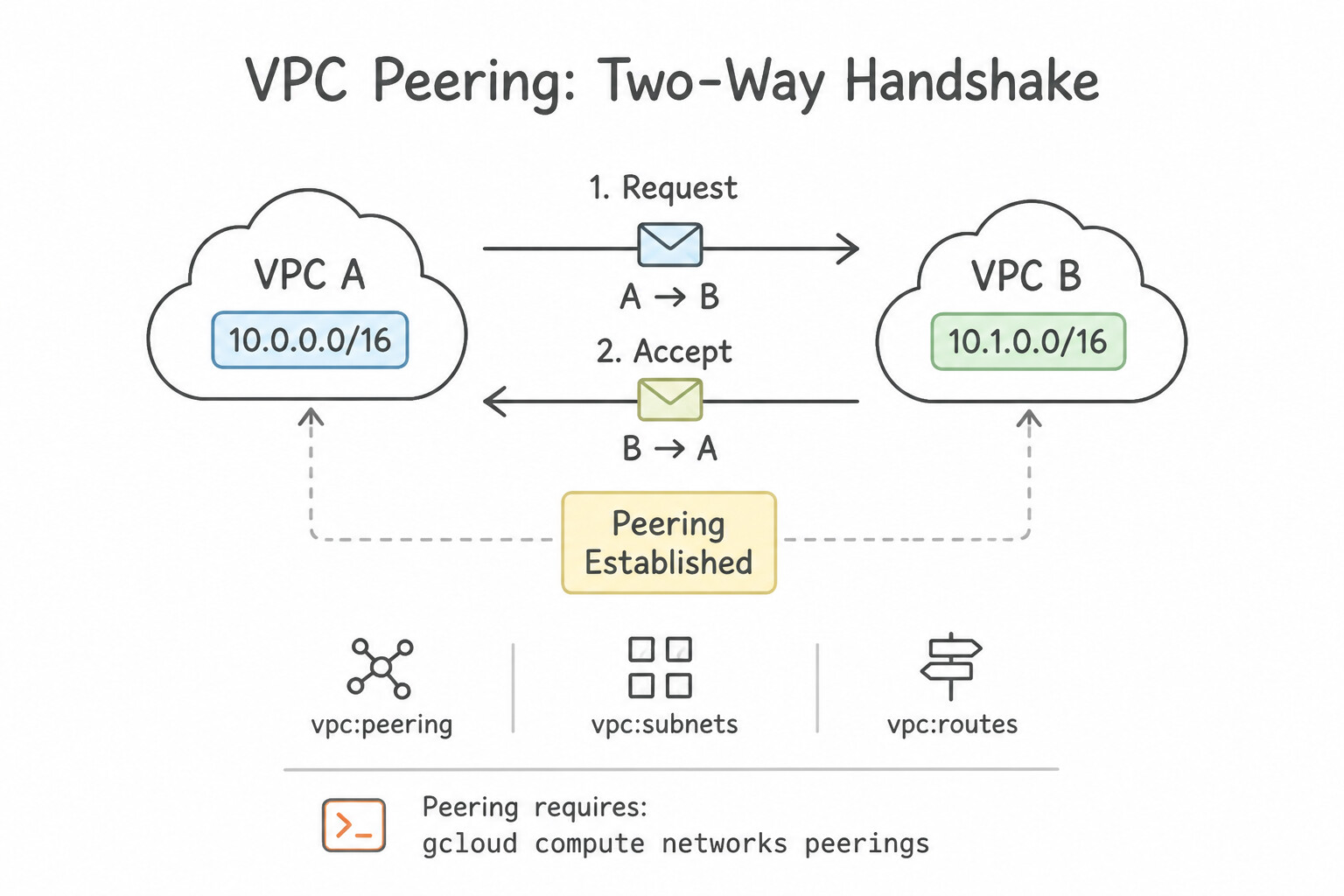
- Two-Way Handshake Requirement: Peering requires
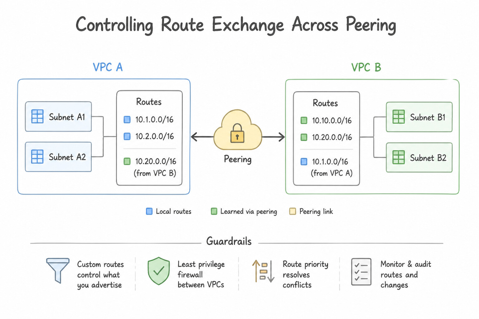
gcloud compute networks peerings createto be executed in both VPC-A (pointing to VPC-B) and VPC-B (pointing to VPC-A). Until both exist, the state remainsINACTIVE. - Controlling Route Exchange Across Peering:
- IPv4 Subnet Routes: Exchanged automatically once
ACTIVE. (To prevent Privately Used Public IP [PUPI] subnet routes from leaking or to enable them, toggle--export-subnet-routes-with-public-ip/--import-subnet-routes-with-public-ip). - Custom Static & Dynamic BGP Routes: Disabled by default! Enable
--export-custom-routeson the hub VPC and--import-custom-routeson the spoke VPC. - Peering Overlap Check: Google Cloud checks across the target VPC and its directly peered neighbors at the time you create or expand a subnet; any CIDR overlap causes the API call to fail immediately.
Key Implementation Patterns
- Dealing with CIDR Block Overlaps: Use Modify the subnet in VPC-B to use a non-overlapping IP address range, such as 10.1.0.0/24. VPC Network Peering requires that the IP address ranges of the subnets in the peered networks do not overlap. (Avoid alternative: Firewall rules control traffic flow but do not prevent the creation of a VPC Peering connection; the failure is due to IP overlap.)
- Exporting Custom Routes to On-Premises: Use Update the peering connection in VPC-A to export custom routes and the peering connection in VPC-B to import custom routes. VPC-A must export its custom routes (including VPN routes) and VPC-B must import them to establish connectivity to on-premises.
Key Takeaways (2.1b)
- VPC Network Peering connects two VPC networks so that resources can communicate using internal IP addresses.
- Peered VPC networks must have completely non-overlapping IP address ranges (CIDR blocks).
- Always plan IP addressing schemas in advance to prevent overlaps in multi-VPC environments.
- If an overlap exists, you must renumber the subnets or use a different connectivity method (like VPN with NAT) before peering can be established.
Consideration 2.1c: Creating Shared VPC and sharing subnets
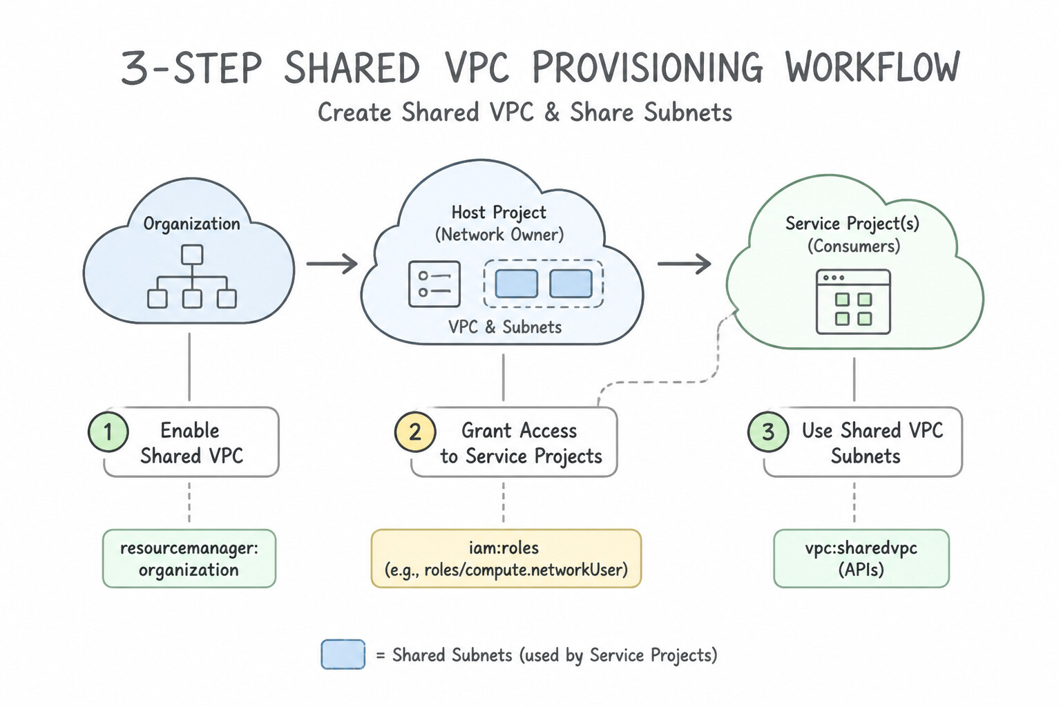
- 3-Step Shared VPC Provisioning Workflow:
- Enable the Host Project:
gcloud compute shared-vpc enable HOST_PROJECT_ID(requiresroles/compute.xpnAdmin). - Attach Service Projects:
gcloud compute shared-vpc associated-projects add SERVICE_PROJECT_ID --host-project=HOST_PROJECT_ID. - Share All Subnets (project-level binding) or Individual Subnets (subnet-level IAM policy binding on
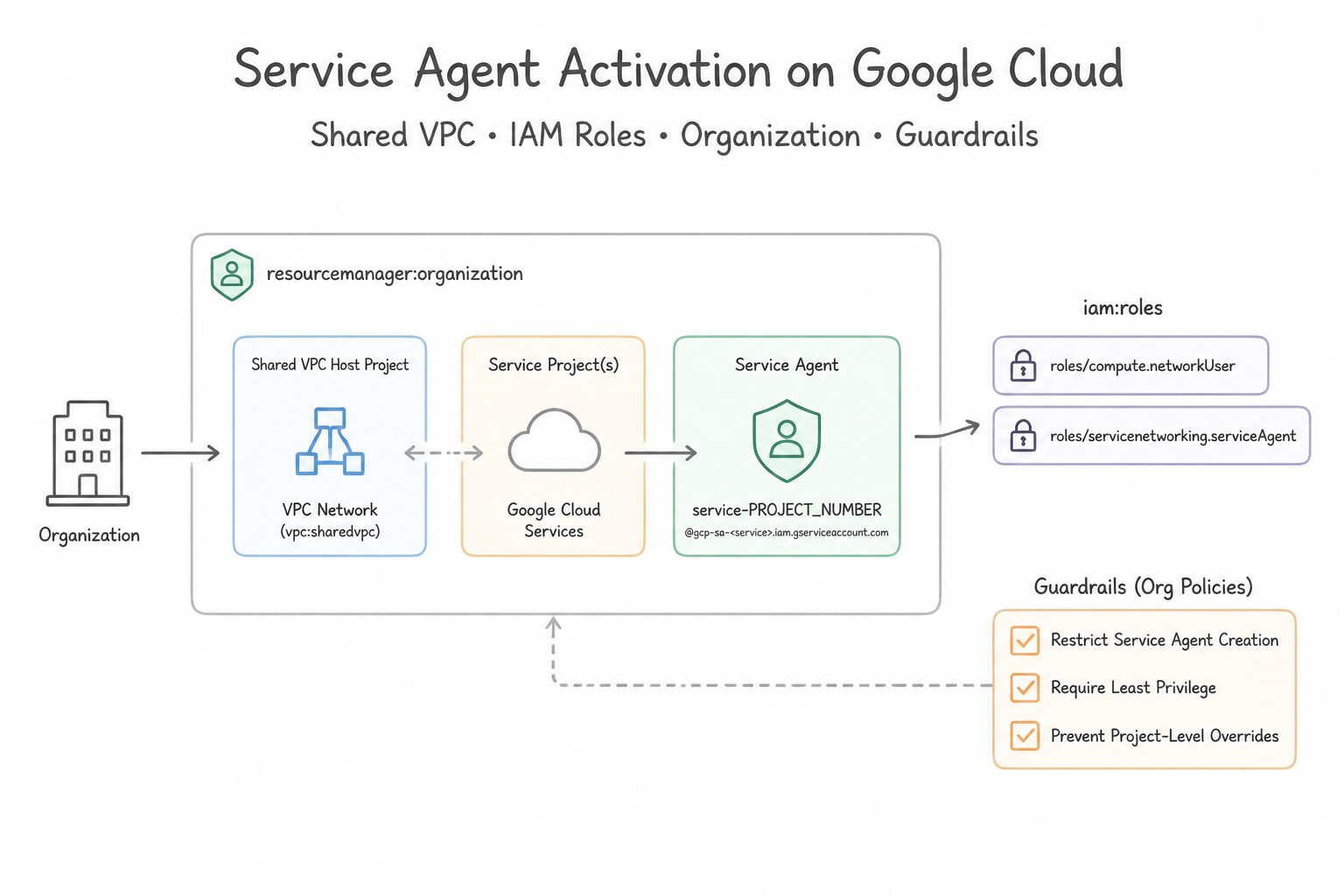
projects/HOST_PROJECT/regions/REGION/subnetworks/SUBNET—production architecture-preferred least-privilege pattern). - Service Agent Activation: When attaching a Service Project that will run Managed Instance Groups (
MIGs) or GKE, always grant subnet-levelroles/compute.networkUserto the Service Project's Google APIs Service Agent (SERVICE_PROJECT_NUMBER@cloudservices.gserviceaccount.com) and, for GKE,roles/container.hostServiceAgentUserat the Host Project level.
Key Implementation Patterns
- Granular Subnet Access Control: Use Grant the Network User role (roles/compute.networkUser) to the admins on the Finance subnet in the host project. Granting compute.networkUser at the subnet level restricts access to only that specific subnet. (Avoid alternative: Project-level permissions apply to all resources (subnets) in the project, failing the isolation requirement.)
- Shared VPC Organization Prerequisites: Use Create a Cloud Identity or Google Workspace account to generate an Organization resource, and migrate the projects into it. Shared VPC requires projects to be inside an Organization resource; migrate the projects from 'No Organization' to a new Organization.
- Service Project Attachment Limits: Use Attach the service project to the host project for Network A. Configure VPC Network Peering between Network A and Network B. A service project can attach to only one host project. Use VPC Network Peering to connect the two Shared VPC networks.
Key Takeaways (2.1c)
- Shared VPC Access: Service Project users need the Network User role to attach resources to a Host Project subnet.
- Least Privilege: Granting the Network User role at the subnet level is best practice for isolating access between teams.
- Resource Ownership: IAM policies for network usage must be set in the Host Project where the network exists.
- Shared VPC functionality requires the existence of an Organization resource.
Consideration 2.1d: Configuring access to Google APIs and services (PGA, public interfaces)
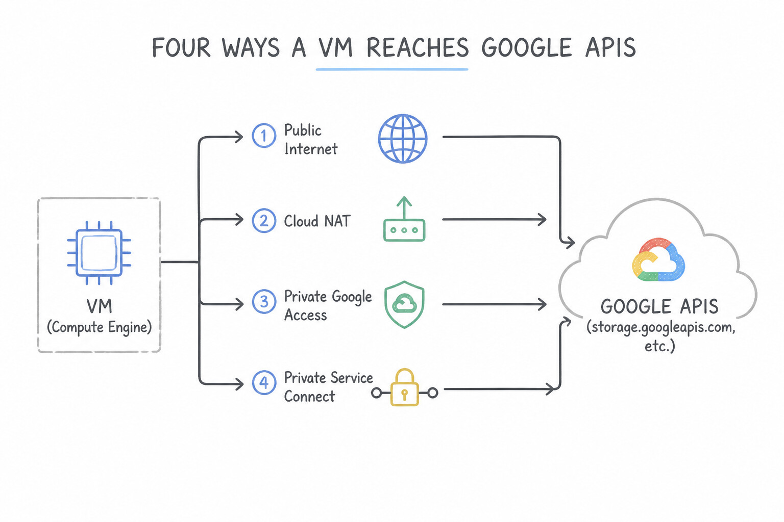
- Four Ways a VM Reaches Google APIs (
storage.googleapis.com, etc.): - Default Public Domains (
*.googleapis.com) with an external IP or Cloud NAT (routes over Google's network, stays inside Google, but uses public VIPs). - Private Google Access (
PGA) viaprivate.googleapis.com(199.36.153.8/30): For VMs without external IPs; supports almost all Google APIs (including non-VPC-SC APIs). - Private Google Access (
PGA) viarestricted.googleapis.com(199.36.153.4/30): Enforces VPC Service Controls and blocks non-compliant APIs. - Private Service Connect (
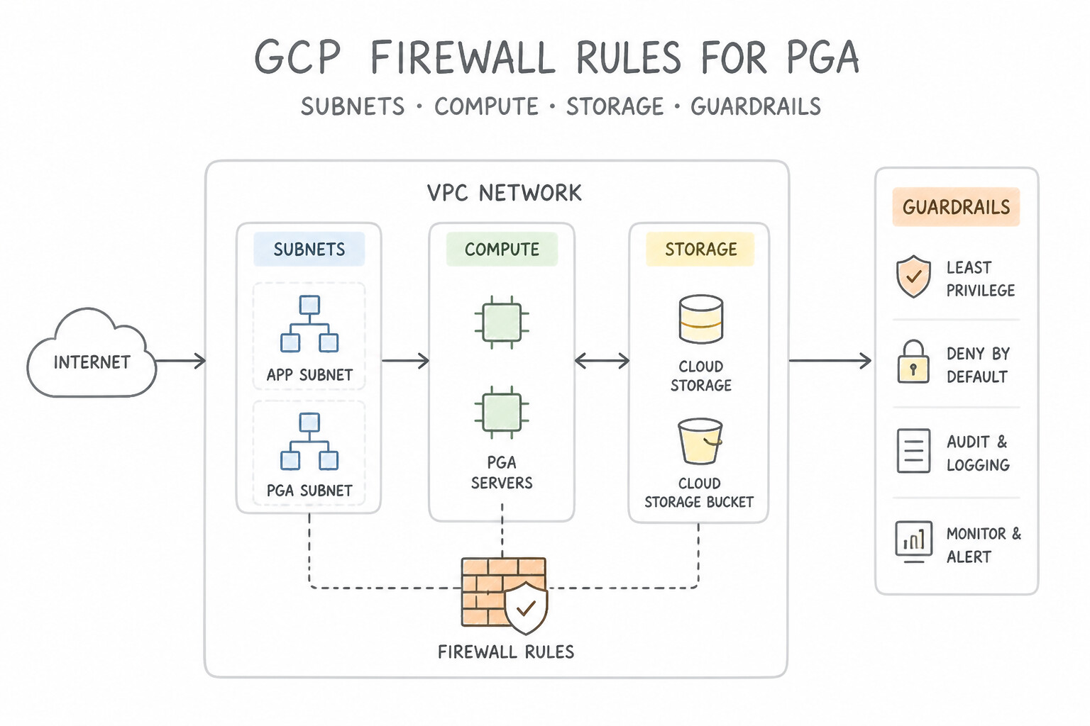
PSC) Endpoint for Google APIs: Creates a customer-selected internal IP (e.g.,10.0.0.100) inside your VPC targeting theall-apisorvpc-scbundle, creating automatic private DNS zones*.p.googleapis.com. - Firewall Rule Requirement for PGA: Even with PGA enabled on the subnet, if your VPC overrides the implied allow-egress rule with an explicit egress
DENYrule (0.0.0.0/0), you must create a higher-priority egressALLOWrule onTCP:443to199.36.153.8/30(or199.36.153.4/30)!
Key Implementation Patterns
- Enabling Access for Internal-Only VMs: Use Enable Private Google Access on the "secure-subnet". Private Google Access allows VMs without external IP addresses to access Google APIs and services when enabled on the subnet. (Avoid alternative: Assigning external IP addresses violates the security compliance requirement stated in the scenario.)
- On-Premises Access to Google APIs: Use Configure on-premises DNS to resolve *.googleapis.com to private.googleapis.com. Advertise the 199.36.153.8/30 IP address range via a custom route advertisement on the Cloud Router. Map the DNS for Google APIs to the private.googleapis.com VIP and advertise its IP range (199.36.153.8/30) over the Cloud Router BGP session.
- Restricting API Access to VPC Service Controls: Use Configure a private DNS zone for *.googleapis.com. Create A records that point to the IP address range 199.36.153.4/30. The restricted.googleapis.com VIP (199.36.153.4/30) limits access to only those Google APIs supported by VPC Service Controls.
Key Takeaways (2.1d)
- VMs without external IP addresses cannot reach Google APIs by default.
- Private Google Access allows VMs with internal IPs to reach Google APIs and services.
- Private Google Access is enabled at the subnet level.
- Google APIs use public IP addresses, but Private Google Access routes traffic to them internally.
Consideration 2.1e: Configuring Vertex AI access
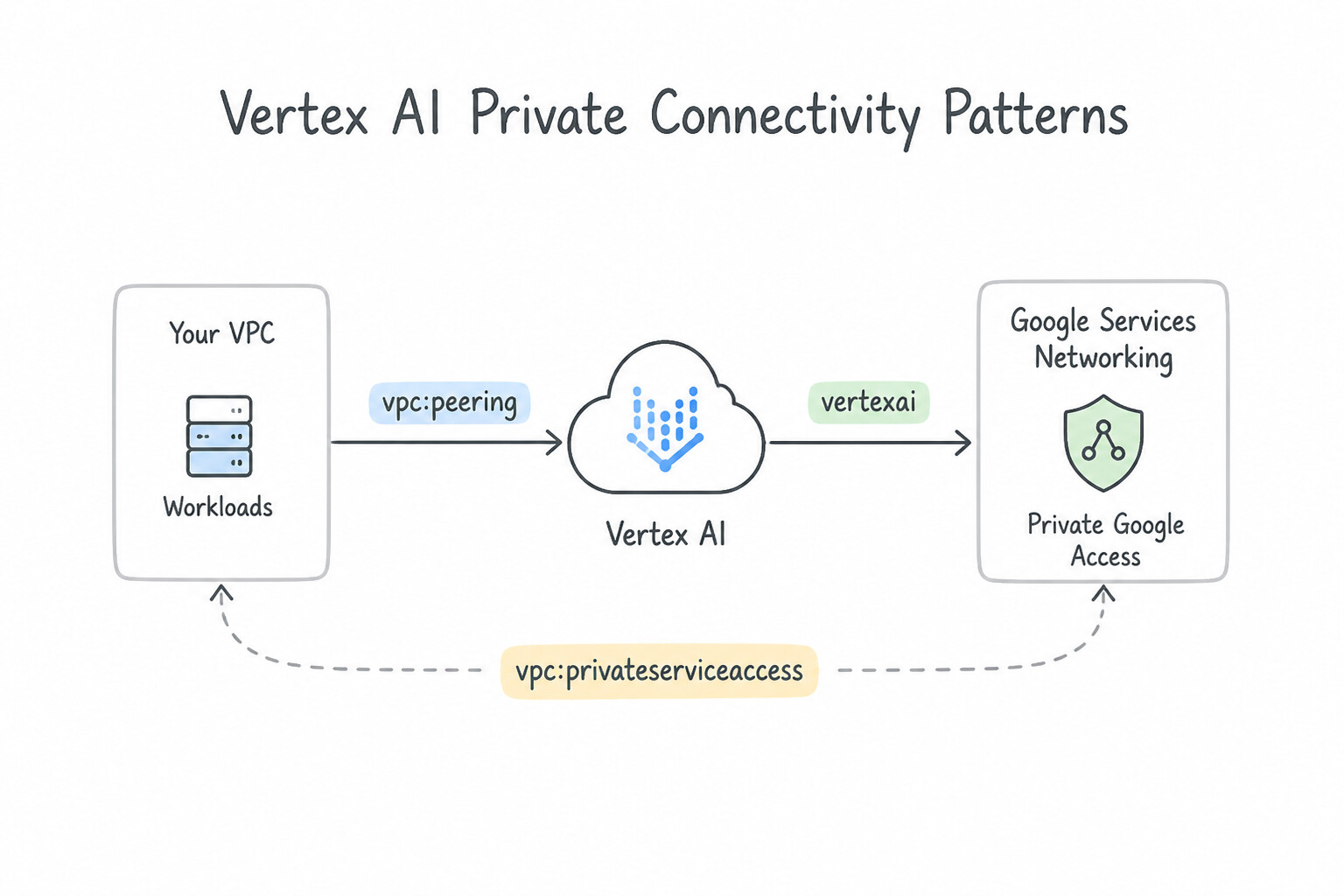
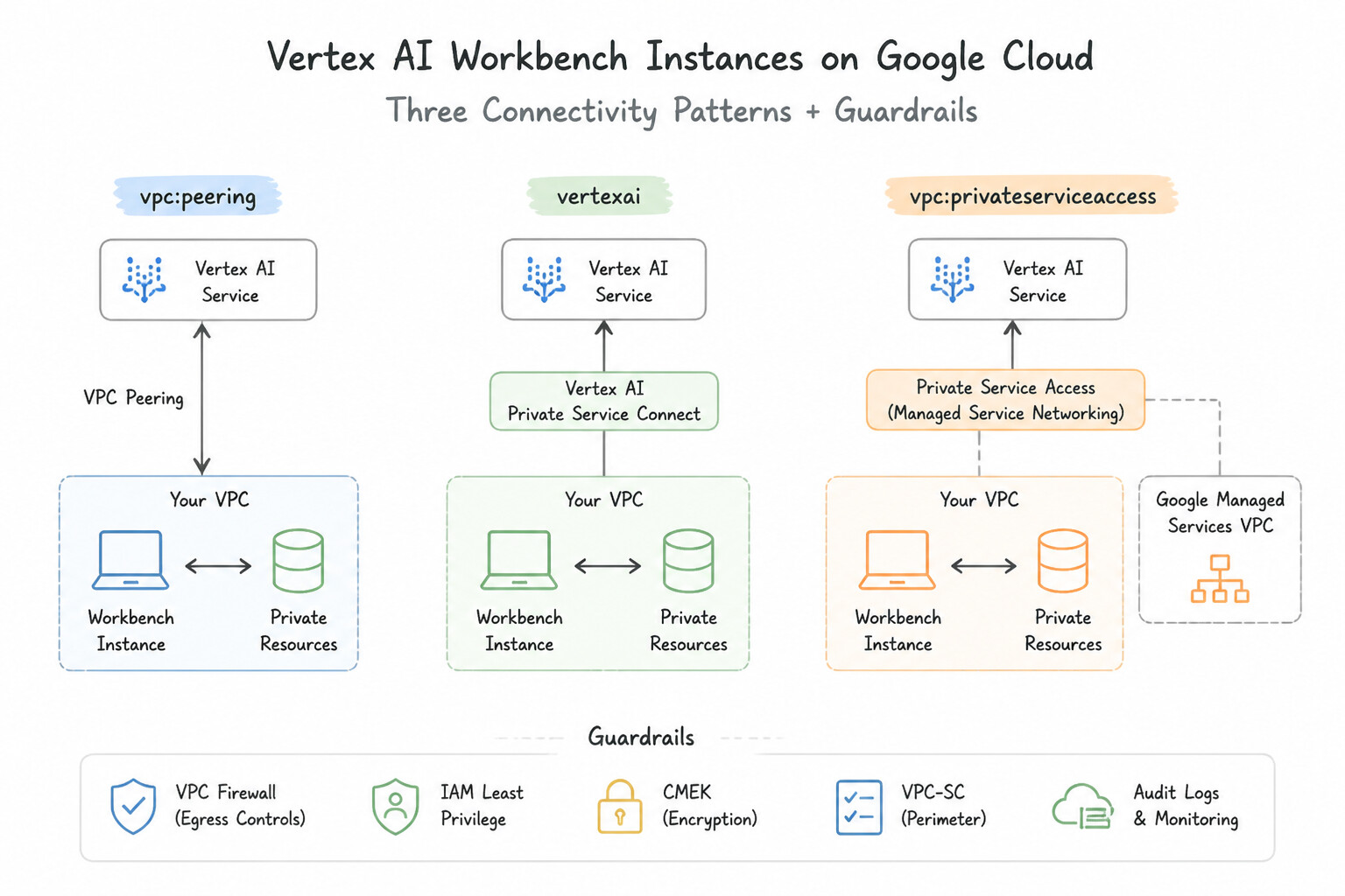
- Vertex AI Private Connectivity Patterns:
- Vertex AI Workbench Instances: Deploy in a subnet with Private Google Access (
PGA) enabled and disable public IP assignment. - Vertex AI Custom Training / Pipelines / Online Prediction: Prefer Private Service Connect (
PSC) Interfaces (Network Attachment) or PSC Endpoints over legacy Private Services Access (PSA) whenever you need to avoid/16IP exhaustion, avoid transitive peering limitations from on-premises, or connect across Shared VPC boundaries with minimal IAM friction.
Key Implementation Patterns
- Initial Setup of Private Service Access for Vertex AI: Use Reserve an internal IP address range in "prod-vpc". Create a private connection to "servicenetworking.googleapis.com" using the reserved range. Vertex AI requires Private Service Access (VPC Peering via Service Networking) to communicate with private IPs in a consumer VPC.
- Handling IP Exhaustion in Service Networking: Use Reserve an additional allocated IP address range. Update the existing private connection to 'servicenetworking-googleapis-com' to include the new range. You can resolve IP exhaustion by allocating a new range and appending it to the existing private connection.
- Private Service Connect (PSC) for Vertex AI API Access: Use Configure a Private Service Connect endpoint. Create a forwarding rule with an internal IP address that targets the global Google API bundle. Private Service Connect allows access to Google APIs via an internal IP address without requiring VPC Network Peering.
Key Takeaways (2.1e)
- Google managed services (like Vertex AI and Cloud SQL) run in a separate 'Producer' VPC.
- To connect your VPC to these services privately, use Private Service Access.
- Private Service Access relies on the Service Networking API and creates a VPC Network Peering connection.
- You must reserve an internal IP range specifically for this peering connection.
Consideration 2.1f: Expanding subnet ranges
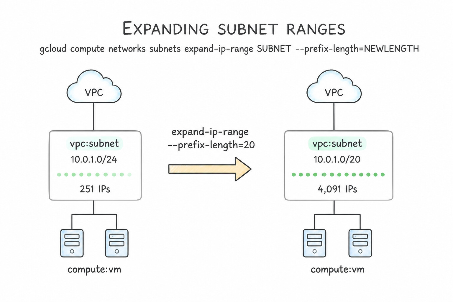
- Rules for
expand-ip-range(gcloud compute networks subnets expand-ip-range SUBNET --prefix-length=NEW_LENGTH): - Zero Downtime: Expanding a primary subnet range (e.g., from
10.10.1.0/24to10.10.0.0/20) causes zero packet loss and zero VM reboots for running instances. - Irreversible (One-Way Operation): You can only decrease the prefix length number (making the block larger, e.g.,
/24→/22). You can never shrink a primary subnet range without deleting and recreating the subnet! - Natural CIDR Boundary Alignment: Extending
10.10.1.0/24to/23automatically expands the block to10.10.0.0/23(10.10.0.0–10.10.1.255); verify that10.10.0.0/24is not already in use in your VPC or any peered VPC! - Primary Ranges Only:
expand-ip-rangeworks only on the primary IPv4 range of a subnet. Secondary IP ranges cannot be expanded—you must add a new secondary range instead.
Key Implementation Patterns
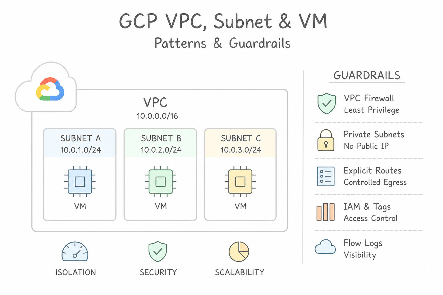
- Basic Primary Range Expansion: Use Update the existing subnet to expand the IP address range to 10.0.0.0/23. You can expand a subnet's primary IP range in place without disrupting running VMs. (Avoid alternative: Migrating VMs to a new subnet causes downtime, which violates the scenario requirements.)
- Subnet Overlap in Same VPC: Use The update fails because the new range overlaps with
subnet-b. The requested /23 range includes the IP space ofsubnet-b, causing a prohibited overlap. (Avoid alternative: VPC subnets do not merge automatically during expansion.) - Peering Constraints on Expansion: Use Create a new subnet in VPC-A with a CIDR range that does not overlap with VPC-B, such as 192.168.2.0/24. Creating a new non-overlapping subnet increases capacity without conflicting with the peered network's address space. (Avoid alternative: Re-peering would fail because the expanded range (192.168.0.0/23) overlaps with the existing range in VPC-B (192.168.1.0/24).)
Key Takeaways (2.1f)
- You can expand a subnet's primary IP range without downtime.
- You cannot shrink a subnet's IP range.
- Decreasing the CIDR prefix (e.g., /24 to /23) increases the number of available IP addresses.
- Secondary ranges are used for Alias IPs and GKE Pods, not typically for the primary interface of standard VMs.
Consideration 2.1g: Configuring VPC Service Controls
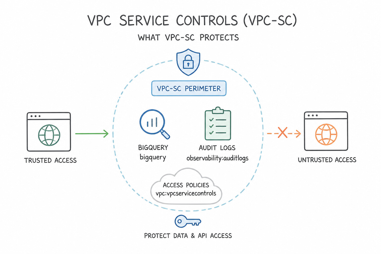
- What VPC-SC Protects: Creates an identity- and network-aware security boundary around multi-tenant Google Cloud APIs (
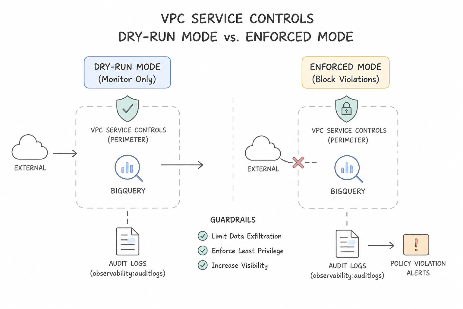
Cloud Storage,BigQuery,Vertex AI,Artifact Registry,Cloud KMS,Spanner) so that even if an attacker steals a valid Service Account token, they cannot read data from outside the perimeter or copy data to an unauthorized external bucket/dataset. - Dry-Run Mode vs. Enforced Mode: Always deploy new perimeters or policy changes in Dry-Run Mode first, inspect VPC Service Controls Audit Logs (
violationReason) in Cloud Logging (protoPayload.metadata."@type"="type.googleapis.com/google.cloud.audit.VpcServiceControlAuditMetadata"), and only promote to Enforced Mode once legitimate flows are allowlisted. - Ingress Rules & Egress Rules vs. Perimeter Bridges:
- Ingress / Egress Rules (Recommended): Directional, fine-grained rules allowing a specific identity (
userorserviceAccount) from a specific source (IPAccess Level, VPC network, or project) to call a specific service and method (storage.googleapis.com/google.storage.objects.get) inside/outside the perimeter. - Perimeter Bridge (Legacy/Broad): Creates a bidirectional link between two perimeters across all protected services—avoid when unidirectional, single-service access is required!
Key Implementation Patterns
- Validating Perimeter Impact with Dry Run Mode: Use Configure the service perimeter in dry run mode. Review the generated audit logs to identify requests that would be denied. Dry run mode logs policy violations without blocking requests, allowing you to validate the configuration safely.
- Enabling Restricted Google APIs VIP: Use Create a private DNS zone for googleapis.com. Add a CNAME record for *.googleapis.com pointing to restricted.googleapis.com. Create an A record for restricted.googleapis.com pointing to 199.36.153.4/30. Restricted.googleapis.com is the required domain for enforcing VPC Service Controls and resolves to 199.36.153.4/30.
Key Takeaways (2.1g)
- VPC Service Controls protect Google API services, not just network traffic.
- Dry Run mode is the standard best practice for testing VPC Service Controls on existing environments.
- Dry Run mode logs violations to Audit Logs but does not block traffic.
- Always analyze dry run logs to create necessary allow exceptions (ingress/egress rules) before enforcing.
Quick Decision Cheat Sheet (Subsection 2.1)
If the Scenario Requires... | Choose This Google Cloud Pattern | Avoid This Common Mistake |
|---|---|---|
"VPC Network Peering status is stuck in INACTIVE" | Have the administrator of the peer VPC create the matching reciprocal peering configuration | Recreating subnets or restarting Cloud Router |
"MIG or GKE creation in a Shared VPC fails with compute.subnetworks.use permission denied" | Grant roles/compute.networkUser to PROJECT_NUM@cloudservices.gserviceaccount.com (and GKE robot SA + hostServiceAgentUser) on the Host subnet | Granting roles/owner inside the Service Project (Host Project resources are governed by Host Project IAM!) |
"Private VMs in a subnet with PGA enabled still cannot reach storage.googleapis.com; VPC has a custom 0.0.0.0/0 egress deny rule" | Add an egress ALLOW firewall rule for TCP:443 to 199.36.153.8/30 (or 199.36.153.4/30) | Enabling Cloud NAT or assigning public IPs to the VMs |
"Prevent an insider with valid IAM credentials from copying confidential Cloud Storage objects to a personal GCP project" | Place the project inside a VPC Service Controls ( VPC-SC) perimeter | Configuring VPC Firewall Rules or Cloud Armor (Cloud Storage API calls do not traverse VM firewall rules!) |
"Allow remote developers on corporate laptops (outside GCP) to access resources inside a VPC-SC perimeter" | Create an Access Context Manager ( ACM) Access Level (matching corporate IP/device policy) and reference it in a VPC-SC Ingress Rule | Disabling VPC Service Controls for storage.googleapis.com |
Further Reading (Subsection 2.1)
- VPC Network Overview - Subnets — Documentation explaining how to expand the primary IP range of a subnet and the limitations regarding shrinking subnets.
- Private services access — Provides an overview of private services access, including the architecture and prerequisites like IP allocation and private connections.
- Configuring private services access — Detailed steps on how to allocate an IP range and create a private connection for services like Cloud SQL.
- VPC firewall rules — Documentation explaining the difference between using network tags and service accounts for firewall rule filtering, emphasizing the security benefits of service accounts.
- VPC Network Peering overview — Review the 'Restrictions' section, which explicitly states that you cannot peer VPC networks with overlapping subnet IP ranges.
- VPC Network Peering - Exchange custom routes — Documentation explaining how to configure peering to export and import custom routes, specifically for scenarios involving VPNs and on-premises access.
Subsection 2.2: Configuring VPC routing
The Big Picture
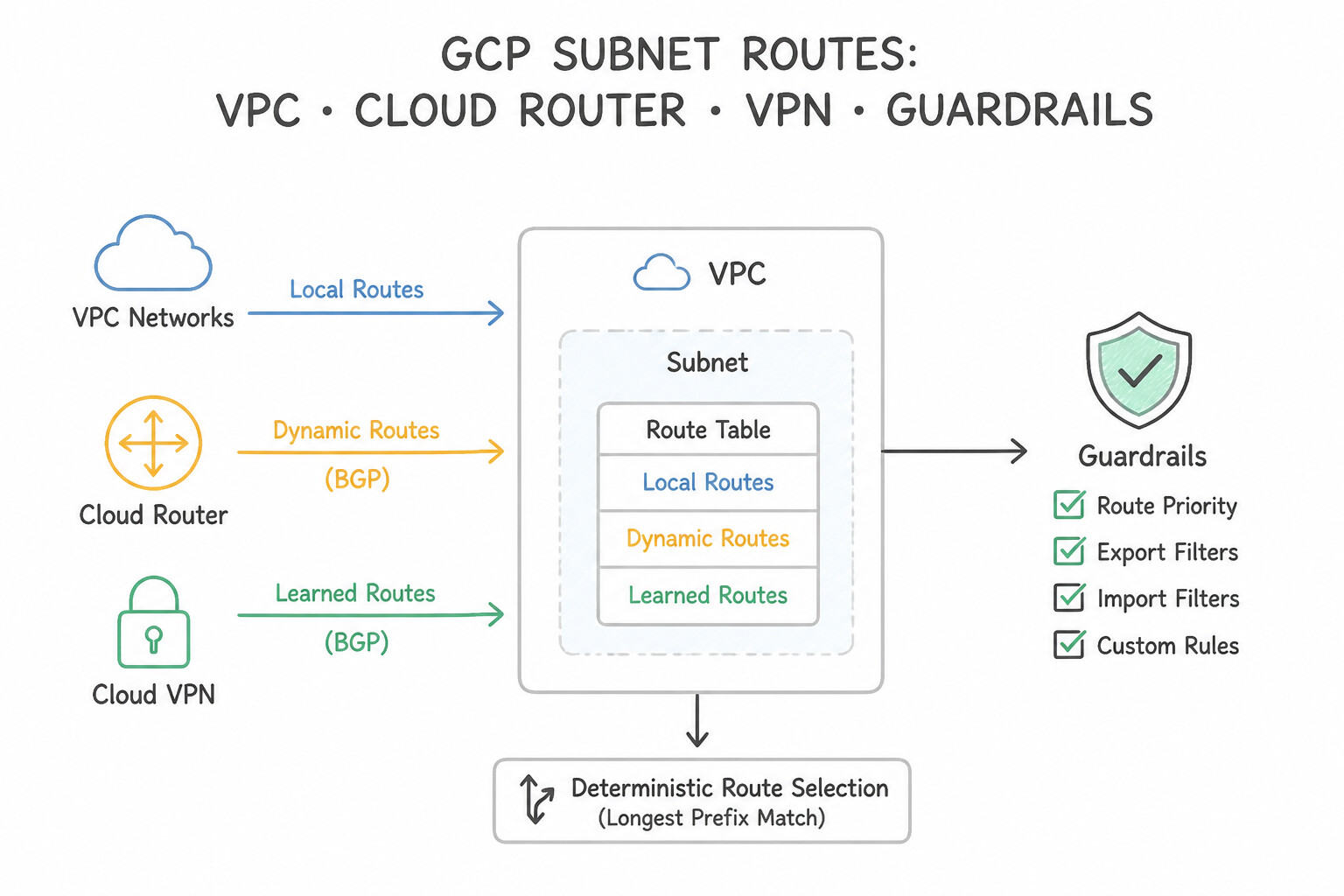
In Google Cloud's software-defined Andromeda network fabric, every VM interface has a virtual routing table synthesized from five sources: Policy-Based Routes (PBR), Local Subnet Routes, Peering/NCC Subnet Routes, Custom Static Routes, and Dynamic BGP Routes learned by Cloud Router. In production, outages happen when engineers misunderstand the strict evaluation precedence between these route types:
- The "Priority Beats Prefix Length" Fallacy (
2.2a,2.2c,2.2d): An engineer has a learned BGP route for10.20.1.0/24with priority1000and creates a static fallback route for10.20.0.0/16with priority10(thinking priority10will override priority1000). It does not! In standard destination-based routing, Longest Prefix Match (LPM) ALWAYS wins first (/24beats/16regardless of priority). Priority (0–65535) only breaks ties between routes with the exact same destination prefix length! - The Local Subnet Route Immortality Rule (2.2g): You cannot delete or override a local VPC subnet route (
10.10.1.0/24) using a standard static route, even with priority0or a/32mask (Google Cloud rejects static routes that match or are more specific than a local subnet range unless they point to special gateways). The only way to intercept east-west traffic destined for a local subnet and steer it through a firewall appliance is Policy-Based Routing (PBR)! - The Deleted VM Next-Hop Blackhole (2.2e): Pointing a custom static route directly at a Next-Hop VM instance (
--next-hop-instance) causes silent packet drops whenever that VM stops, fails a guest OS process, or gets replaced during maintenance. Production architectures always point custom routes and Policy-Based Routes at an Internal Passthrough Network Load Balancer (--next-hop-ilb) backed by a health-checked Managed Instance Group.
Consideration 2.2a: Configuring static and dynamic routing with Cloud Router
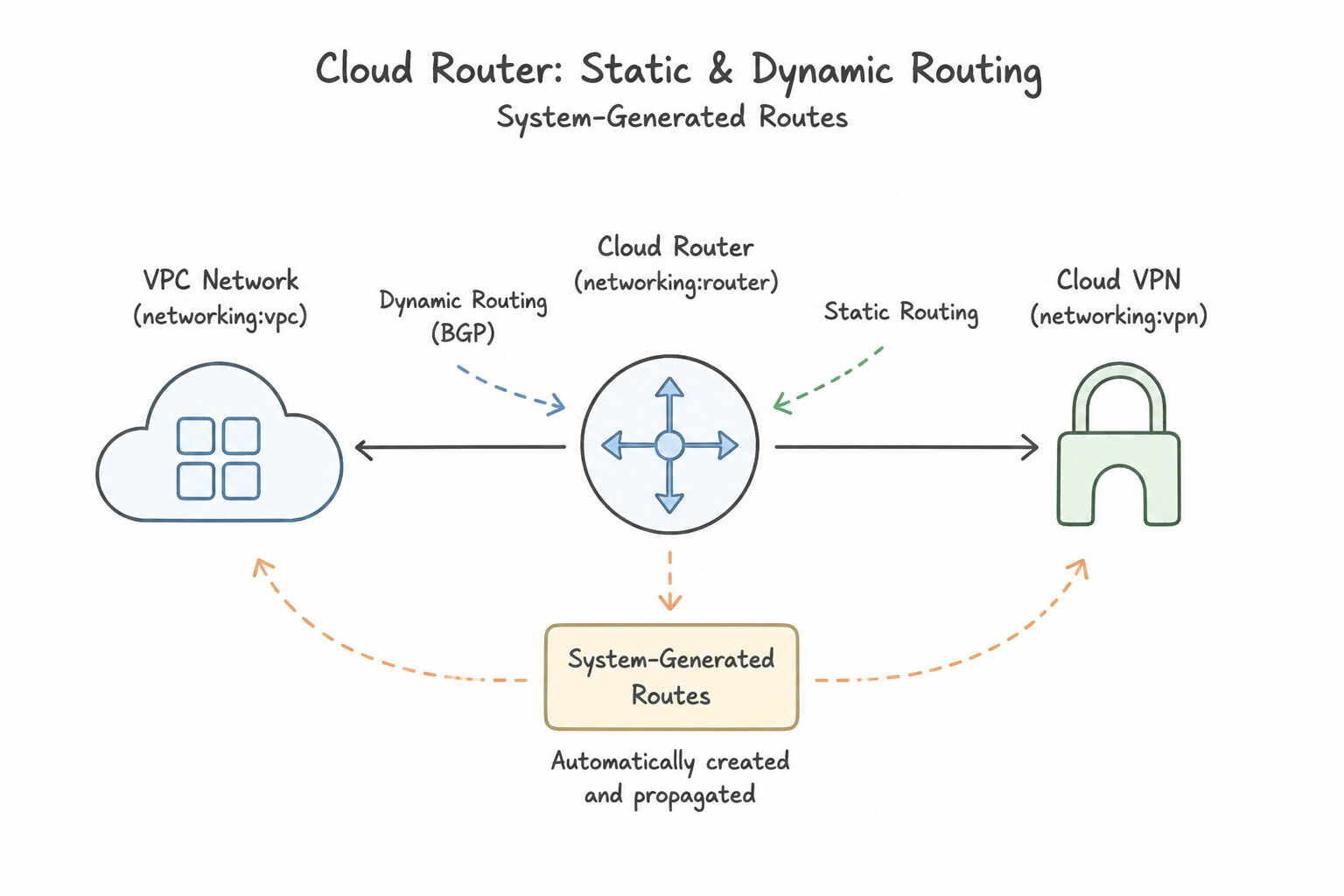
- System-Generated Routes:
- Subnet Routes: Created automatically for every primary and secondary subnet CIDR (
Priority 0); cannot be deleted unless the subnet is deleted. - Default Internet Route (
0.0.0.0/0→default-internet-gateway): Created automatically (Priority 1000); can be deleted or replaced with a custom static route pointing to an NVA Internal Load Balancer or proxy for forced egress inspection. - Custom Static Routes vs. Dynamic Routes (Cloud Router):
- Static Routes: Manually defined (
--next-hop-ilb,--next-hop-instance,--next-hop-address,--next-hop-vpn-tunnel,--next-hop-gateway). If a static route points to--next-hop-instanceor--next-hop-addresswithout a health check and the VM crashes, the route remains in the routing table and blackholes traffic! - Dynamic Routes (
Cloud Router): Learned via eBGP over HA VPN, Cloud Interconnect, or Router Appliances. Automatically withdrawn within seconds (or milliseconds with BFD) when a tunnel or peer fails.
Key Implementation Patterns
- Cross-Region VPN Propagation: Use Change the dynamic routing mode of the VPC network to Global. Global dynamic routing allows Cloud Routers to share learned routes with subnets in all regions, not just the local region. (Avoid alternative: HA VPN uses dynamic routing (BGP), not static routes, and this does not address the cross-region scope.)
- Next-Hop Internal Load Balancer: Use Create a custom static route with destination 0.0.0.0/0. Set the next hop to the forwarding rule of the load balancer. Use a static route with the destination 0.0.0.0/0 and set the next hop to the load balancer's forwarding rule. (Avoid alternative: Instance groups are not valid next-hop targets for VPC routes; you must target the load balancer forwarding rule.)
- Influencing Egress Traffic with MED: Use Configure the BGP session for Link A with a lower base priority value than the BGP session for Link B. Lower base priority values indicate a more preferred route for egress traffic leaving the VPC. (Avoid alternative: Higher priority values result in a less preferred route, causing traffic to use the other link.)
Key Takeaways (2.2a)
- VPC Dynamic Routing Mode determines the scope of route learning and advertisement.
- Regional mode (default) restricts Cloud Router updates to the local region.
- Global mode allows Cloud Router to propagate routes to all regions in the VPC.
- Cross-region access to on-premises networks via a single VPN gateway requires Global dynamic routing.
Consideration 2.2b: Configuring global or regional dynamic routing
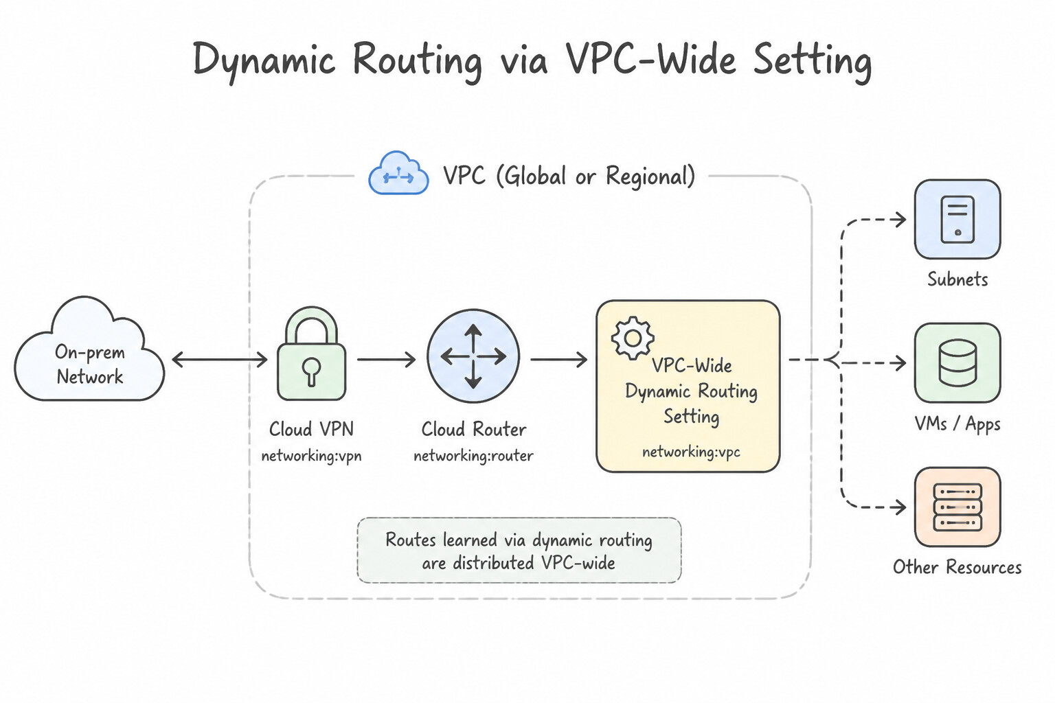
- VPC-Wide Setting: Dynamic routing mode (
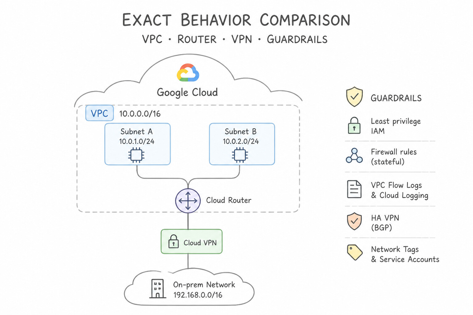
REGIONALvs.GLOBAL) is configured on the VPC network resource itself (gcloud compute networks update VPC_NAME --bgp-routing-mode=GLOBAL), not on individual Cloud Routers. - Exact Behavior Comparison:
REGIONALMode: Cloud Router only advertises subnets located in the same region as the Cloud Router, and learned on-premises BGP routes are only programmed into subnets in that same region.GLOBALMode: Cloud Router advertises all subnets across all regions of the VPC (unless overridden by Custom Route Advertisements), and learned on-premises BGP routes are programmed into every region of the VPC—enabling seamless cross-region HA failover.
Key Implementation Patterns
- Enabling Cross-Region VPN Access: Use Change the dynamic routing mode of the VPC network to Global. Global dynamic routing allows a Cloud Router to advertise subnets from all regions, not just its own. (Avoid alternative: Creating a new tunnel works but adds unnecessary cost and complexity compared to changing the routing mode.)
- Strict Traffic Geo-Isolation Compliance: Use Set the VPC network dynamic routing mode to Regional. Regional dynamic routing restricts Cloud Routers to advertise only the subnets located in the same region as the router. (Avoid alternative: Global dynamic routing advertises subnets from all regions, which contradicts the requirement for regional isolation.)
- High Availability with Cross-Region Failover: Use Update the VPC network configuration to use Global dynamic routing. Global dynamic routing allows Cloud Routers to advertise subnets from all regions, enabling cross-region failover. (Avoid alternative: Cloud Routers are regional resources and cannot manage connections in a different region.)
Key Takeaways (2.2b)
- VPC Dynamic Routing Mode controls the scope of routes advertised by Cloud Routers.
- Regional mode (default) limits advertisements to the router's local region.
- Global mode extends advertisements to all subnets in the VPC, regardless of region.
- Changing this mode affects all Cloud Routers in the VPC network.
Consideration 2.2c: Implementing route priorities and tags
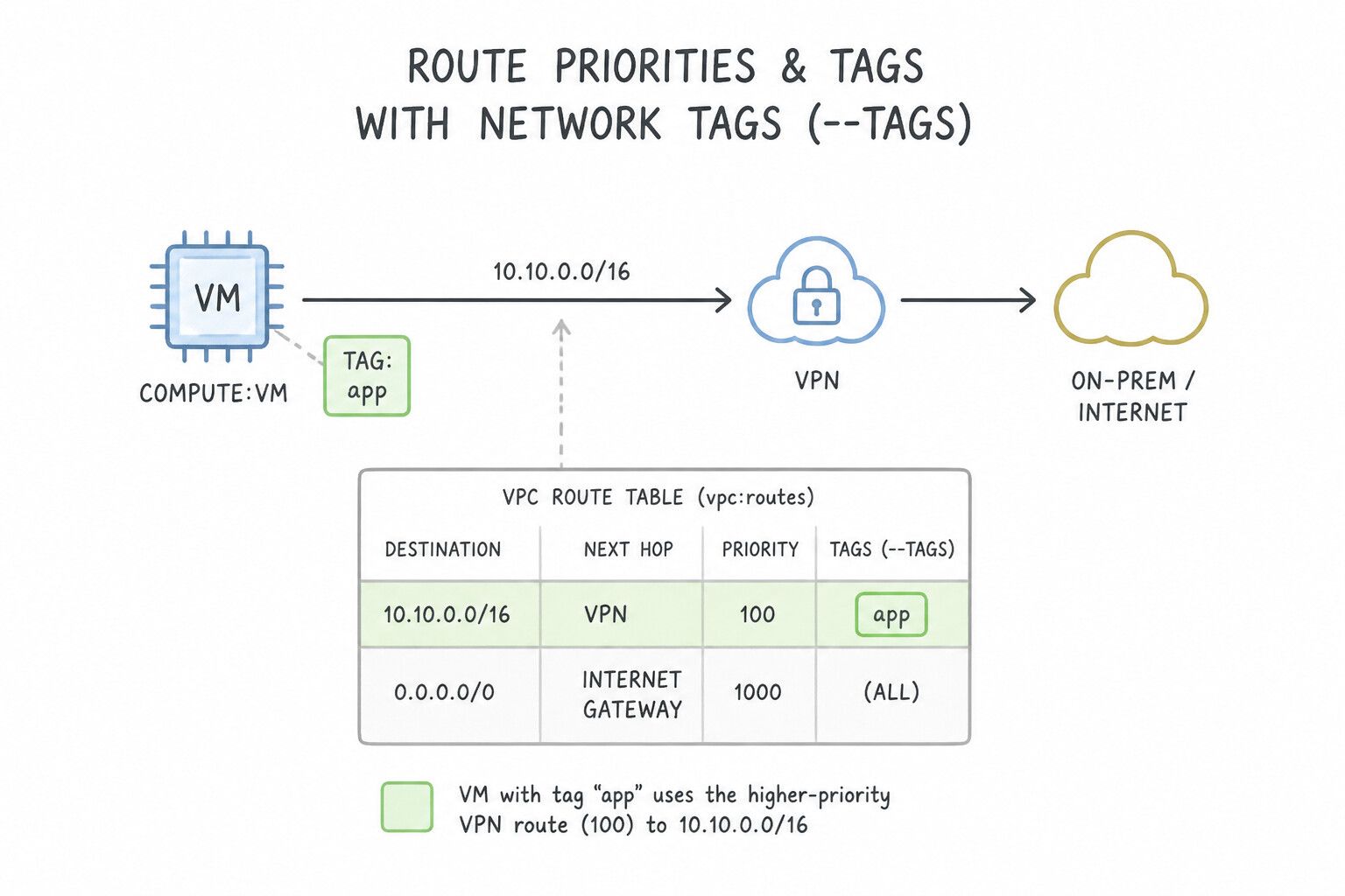
- Network Tags on Static Routes (
--tags): - You can scope a custom static route so it applies only to source VMs bearing a specific Network Tag (e.g.,
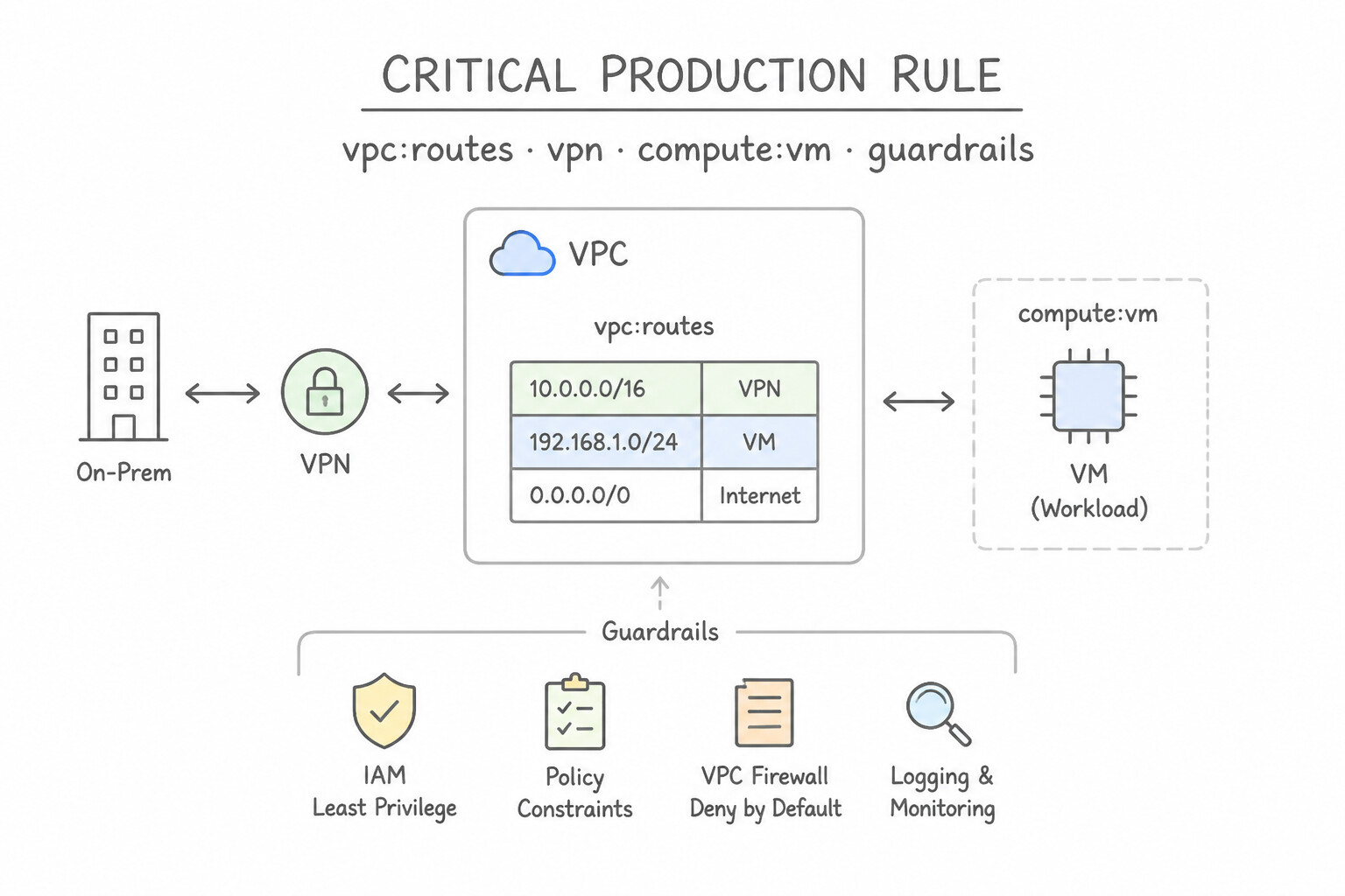
--tags=prod-db). - Critical Production Rule: Before Google Cloud even compares prefix lengths (
LPM) or priorities, it discards any tagged static route whose tag does not match the sending VM. However, for a VM that does have the tag, both tagged and untagged routes are candidates—so an untagged/24route still beats a tagged/16route via Longest Prefix Match! - Limitation: Dynamic BGP routes learned by Cloud Router cannot use network tags (they always apply to all VMs in the region/VPC).
- Route Priority (
0to65535, Default1000): Lower integer = higher preference (100beats1000). Only evaluated after Longest Prefix Match is tied!
Key Implementation Patterns
- Active/Passive VPN Configuration: Use Set the priority for the Tunnel A route to 100 and the priority for the Tunnel B route to 200. Google Cloud routes prefer lower priority values. Setting Tunnel A to 100 and Tunnel B to 200 makes Tunnel A the primary path. (Avoid alternative: Lower priority values are preferred. This configuration would make Tunnel B the primary path instead of Tunnel A.)
- Canary Routing Updates: Use Add a unique network tag to the test VMs. Create a static route to the firewall appliance and specify this tag in the target tags field. Network tags allow you to apply specific routes to a subset of instances without affecting the rest of the network.
- Longest Prefix Match vs. Priority: Use The router selected Route B because it provides the longest prefix match for the destination. The longest prefix match (most specific route) always overrides route priority. (Avoid alternative: Lower integer values indicate higher priority in Google Cloud, but prefix specificity is evaluated first.)
Key Takeaways (2.2c)
- Google Cloud routes use priority integers to resolve conflicts between identical destination prefixes.
- Lower integer values indicate higher priority (e.g., 100 is preferred over 200).
- Equal priorities for the same destination result in ECMP (traffic balancing).
- Staggered priorities (low vs. high) are used to implement Active/Passive failover.
Consideration 2.2d: Designing priorities with global dynamic routing
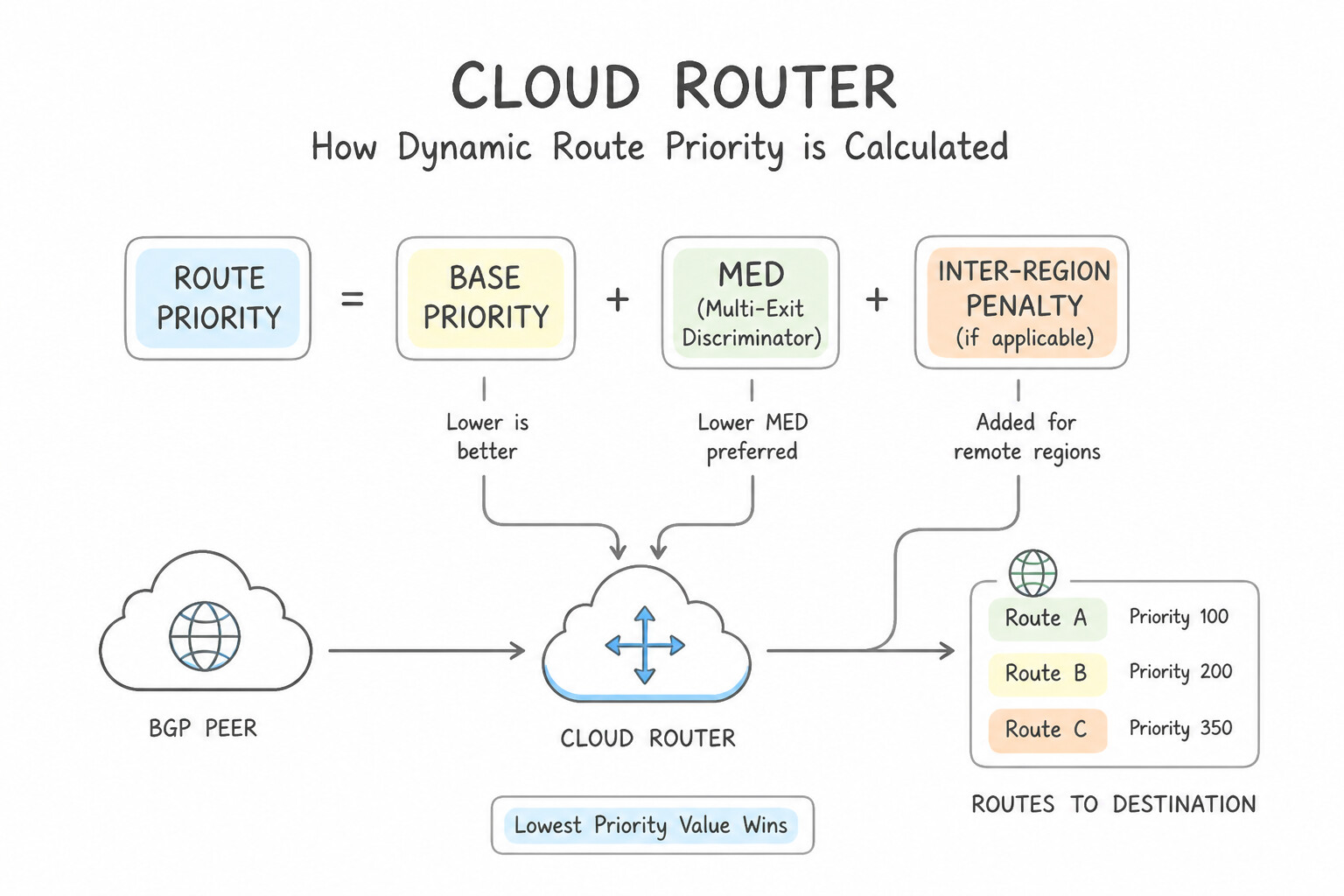
- How Cloud Router Calculates Dynamic Route Priority (
Base Priority + MED + Inter-Region Penalty): - On-premises routers advertise a Multi-Exit Discriminator (
MED) (or you set an advertised route priority on Cloud Router). - When
GLOBALdynamic routing is enabled under Legacy best path selection, Google Cloud adds an automatic inter-region cost (201to9999) to routes learned in a remote region so VMs inus-central1always prefer theus-central1Interconnect over theeurope-west1Interconnect unless theus-central1link fails (or unless you intentionally set a much higher MED penalty on the local link that exceeds the inter-region cost). - Precedence of Policy-Based Routing (
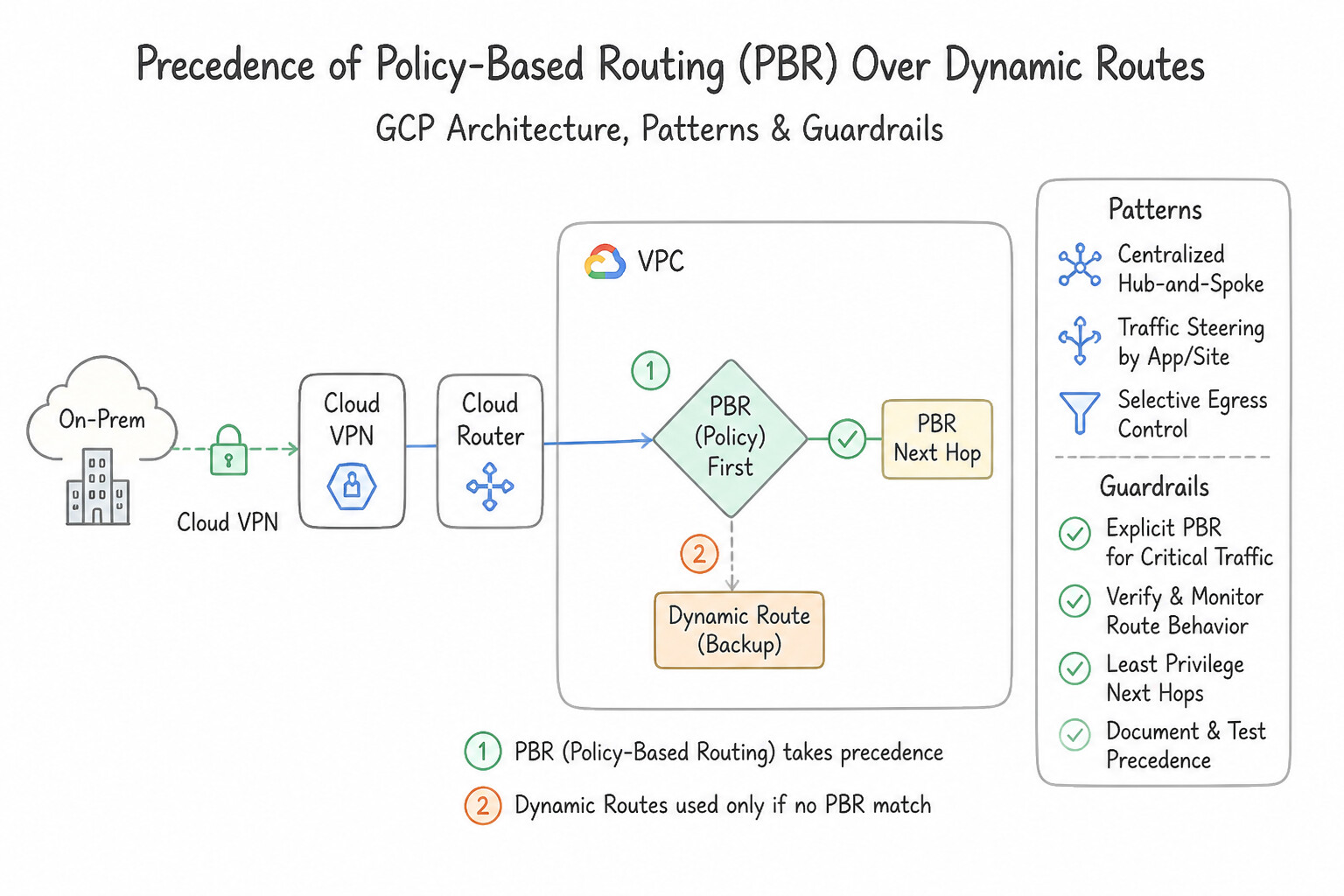
PBR) Over Dynamic Routes: Policy-Based Routes are evaluated before all static, subnet, and BGP dynamic routes—allowing you to steer traffic into an inspection appliance before it ever hits a Cloud Router BGP route.
Key Implementation Patterns
- Active-Passive Configuration for HA VPN: Use Configure the Cloud Router BGP session for Tunnel A with an Advertised Route Priority of 100 and Tunnel B with an Advertised Route Priority of 200. Lower MED values indicate higher priority. Setting Tunnel A to 100 and Tunnel B to 200 ensures Tunnel A is preferred.
- Enabling ECMP for Aggregate Bandwidth: Use Configure the BGP sessions on the Cloud Router with the same advertised route priority. ECMP requires identical route priorities (MED values) on the BGP sessions to balance traffic across multiple links. (Avoid alternative: Unique priorities on static routes force traffic to a single path rather than load balancing it.)
- Global Dynamic Routing and Regional Failover: Use Edit the VPC network properties to set the Dynamic routing mode to Global. Global dynamic routing allows a Cloud Router to advertise subnets from all regions, not just its own. (Avoid alternative: This creates unnecessary infrastructure and does not utilize the existing VPN connection as requested.)
Key Takeaways (2.2d)
- Advertised Route Priority on Cloud Router maps to the BGP MED attribute.
- A lower priority value (e.g., 100) indicates a higher preference to the peer router.
- To achieve Active/Passive routing for ingress traffic, assign a lower MED to the primary tunnel and a higher MED to the backup tunnel.
- Ingress traffic is influenced by what GCP advertises (MED); Egress traffic is influenced by what GCP receives (Local Preference/MED from peer).
Consideration 2.2e: Using internal load balancer as next hop
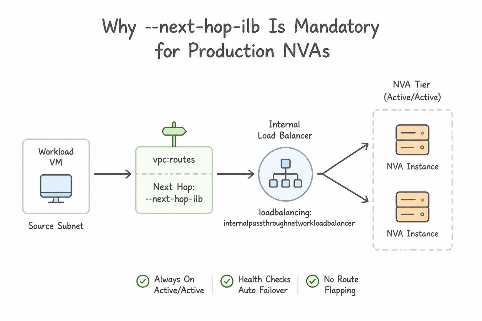
- Why
--next-hop-ilbIs Mandatory for Production NVAs: - Pointing a route's next hop to an Internal Passthrough Network Load Balancer (
--next-hop-ilb) gives you automated health-checked failover, active-active ECMP scaling across multiple NVA VMs, and symmetric hashing (ensuring forward and return packets of a 5-tuple flow hit the exact same stateful firewall VM). - Key Configuration Requirements:
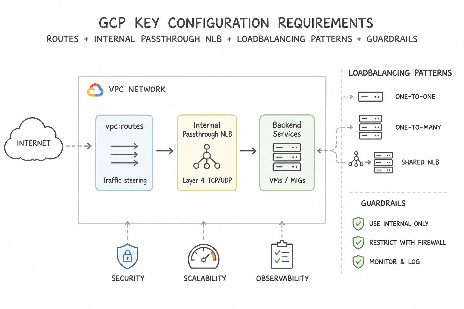
- The Next-Hop ILB must be an Internal Passthrough Network Load Balancer (Layer 4)—Application Load Balancers and Proxy Network Load Balancers cannot be used as route next hops!
- Enable
--can-ip-forwardon all backend NVA VM instances. - Enable Global Access on the Internal Passthrough Load Balancer if routes in other regions need to use that ILB as a next hop.
- When multiple custom routes have identical prefix lengths and priorities pointing to different Next-Hop ILBs, Google Cloud distributes traffic across them via ECMP.
Key Implementation Patterns
- High Availability NVA Deployment: Use Set the next hop of the route to the internal IP address of the load balancer's forwarding rule. When using HA NVAs, the VPC route next hop must be the Internal Load Balancer forwarding rule to ensure redundancy. (Avoid alternative: A Managed Instance Group is not a valid next hop type for a VPC static route.)
- Handling Asymmetric Return Traffic: Use Configure Source NAT (SNAT) on the NVA instances. SNAT forces the destination to reply to the NVA's IP address, ensuring the return traffic goes through the NVA. (Avoid alternative: Global access enables cross-region access, not return traffic symmetry.)
Key Takeaways (2.2e)
- VPC Static Routes control traffic flow based on destination IP ranges.
- To make Network Virtual Appliances (NVAs) highly available, place them behind an Internal Load Balancer (ILB).
- Use the ILB's forwarding rule as the 'next hop' in your static route to distribute traffic across healthy instances.
- Never point a high-availability route to a single VM instance.
Consideration 2.2f: Configuring custom route import/export over VPC Peering
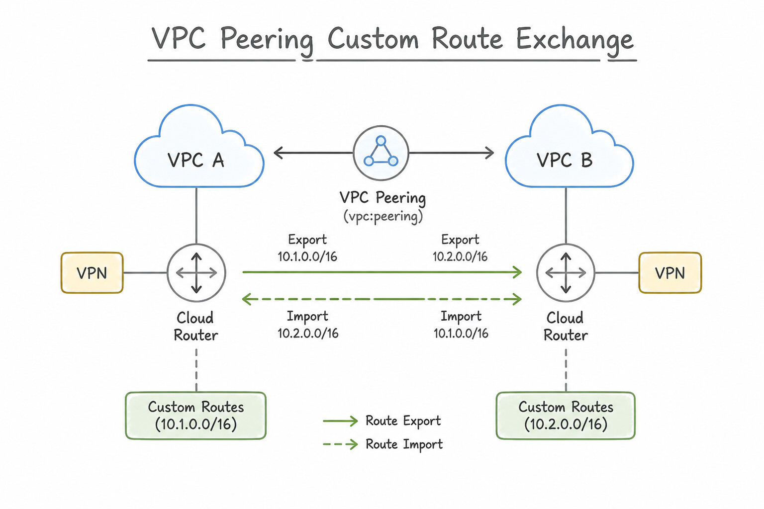
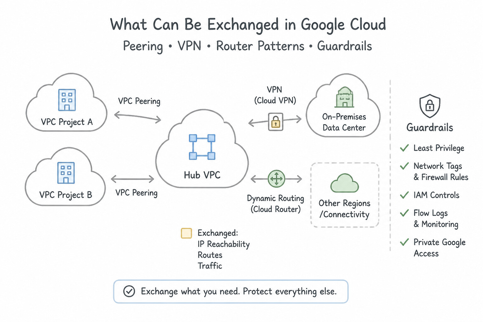
- VPC Network Peering Custom Route Exchange:
- Requires
--export-custom-routeson the exporter VPC and--import-custom-routeson the importer VPC. - What Can Be Exchanged: Custom static routes and dynamic BGP routes learned by Cloud Router.
- What Can NEVER Be Exchanged Over VPC Peering:
- Policy-Based Routes (
PBR) are strictly local to the VPC where they are created and are never exported over VPC Network Peering! - Static routes filtered by Network Tags (
--tags) are never exported over VPC Network Peering! (Only untagged custom routes are exported). - Transitive Peering Routes (routes learned from a third peered VPC) are never re-exported.
- Network Connectivity Center (
NCC) Route Exchange: - NCC automatically exchanges subnet routes among VPC spokes (and dynamic BGP routes with Hybrid spokes), and supports IP/CIDR Range Filters on spokes to allowlist or block specific prefixes from being advertised into the NCC Hub.
Key Implementation Patterns
- Hub-and-Spoke Hybrid Connectivity: Use Update the peering connection in the Hub VPC to export custom routes and the peering connection in the Spoke VPC to import custom routes. Transitive routing to on-premises via a Hub VPC requires exporting custom routes on the Hub side and importing them on the Spoke side.
- Centralized Internet Egress via NVA: Use Update the peering connection in the Security VPC to export custom routes. Update the peering connection in the App VPC to import custom routes. Static routes are custom routes. You must export them from the VPC where they exist and import them in the peered VPC.
- Asymmetric Routing Configuration: Use Edit the peering connection in "vpc-a" to export custom routes. Edit the peering connection in "vpc-b" to import custom routes. To share routes from A to B, A must export and B must import. Avoiding the reverse configuration prevents A from learning B's routes.
Key Takeaways (2.2f)
- VPC Network Peering only exchanges subnet routes by default.
- Routes learned via Cloud VPN (BGP) are considered custom routes.
- To enable transitive connectivity (Spoke to On-prem via Hub), you must configure 'Export custom routes' on the Hub peering connection and 'Import custom routes' on the Spoke peering connection.
- You cannot use a next hop located in a peered VPC for a static route.
Consideration 2.2g: Configuring policy-based routing
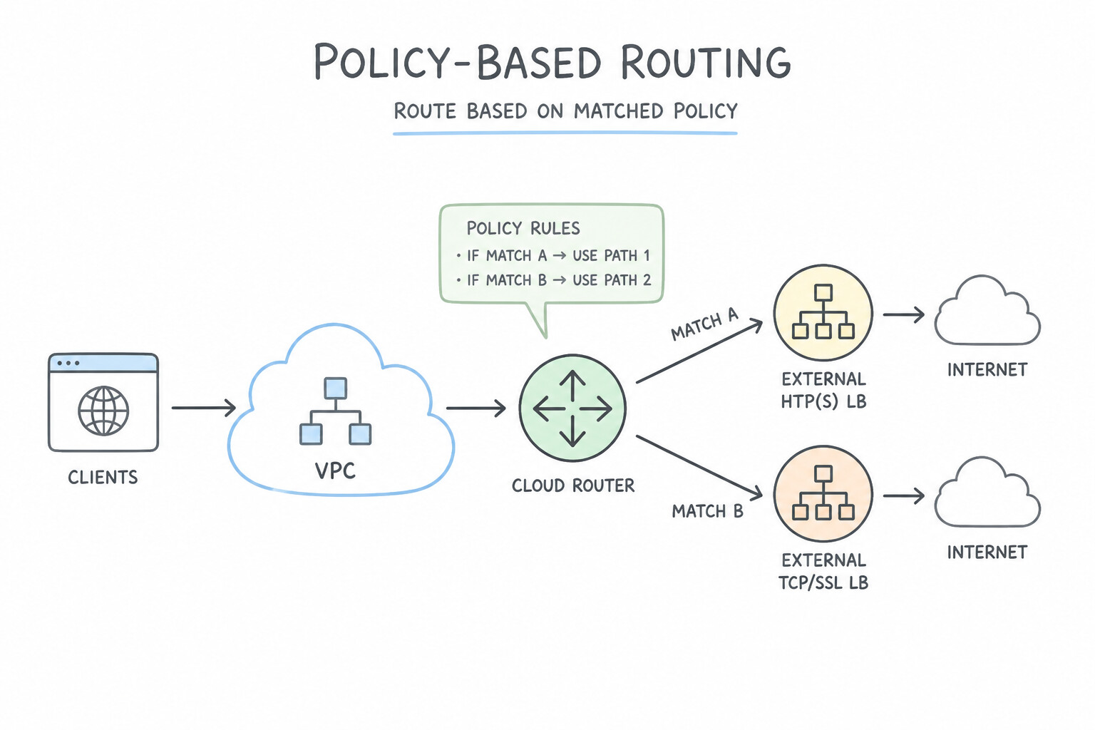
- What Makes Policy-Based Routing Unique:
- Standard VPC routes only inspect the Destination IP of a packet.
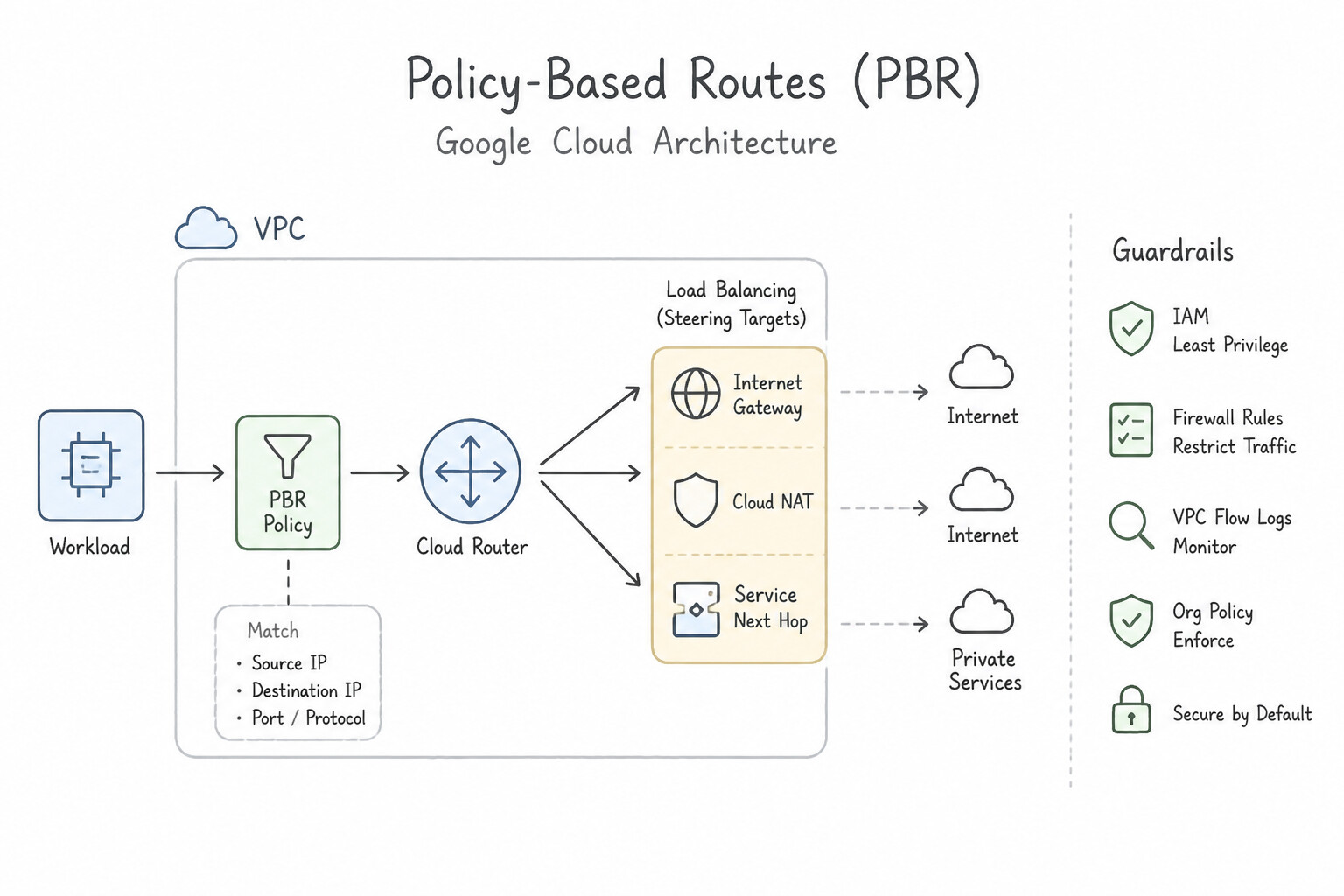
- Policy-Based Routes (
PBR) inspect Source IP CIDR, Destination IP CIDR, and Layer 4 Protocol (TCP,UDP,ICMP, orALL), and are evaluated at the very top of the routing pipeline—even before local subnet routes! - Top 3 architectures Use Cases for PBR:
- East-West Intra-VPC Inspection: Forcing traffic between two subnets in the same VPC (or to a PSC endpoint) to detour through a Next-Hop Internal Passthrough Load Balancer (
NVA), overriding the default local subnet route. - Source-Based Routing: Routing traffic from specific source subnets (
10.1.0.0/24) to a specific Next-Hop ILB while other source subnets follow standard BGP routes. - Return-Path Symmetry for Multi-NIC NVAs: Ensuring return traffic from an application subnet goes back through the NVA's Internal Load Balancer rather than taking a direct shortcut.
- Preventing Infinite Routing Loops with PBR: When creating a PBR that matches
0.0.0.0/0or a local subnet and forwards to an NVA Next-Hop ILB, you must scope the PBR using Network Tags (--tags) on the source VMs (or exclude the NVA VMs' tags/source IPs) so packets leaving the NVA after inspection are not matched by the same PBR again in an infinite loop!
Key Implementation Patterns
- Routing Traffic Through Transparent Firewalls: Use Create a policy-based route. Set the source to the 'secure-workloads' subnet range and the next hop to the ILB forwarding rule. PBR allows routing based on the source subnet, and pointing to an ILB ensures high availability for the firewall fleet.
- Handling Asymmetric Routing in Multi-NIC VMs: Use Configure a policy-based route in the VPC containing nic1 that matches the source IP address of nic1 and sets the next hop to the default internet gateway. Policy-based routing allows you to route traffic based on the source IP address, forcing return traffic from nic1 to use the nic1 gateway.
- Creating Routing Exceptions: Use Modify the PBR policy to match specific destination ports, such as 80 and 443, effectively excluding the internal tool's traffic from the policy. Since PBR cannot match destination IPs, you must restrict the policy to specific ports (e.g., 80/443) so that other traffic falls back to standard routing.
Key Takeaways (2.2g)
- Use Policy-Based Routing (PBR) when routing decisions must be based on the source IP or subnet.
- Always point routes to an Internal Load Balancer (ILB) forwarding rule rather than a single instance IP when using network virtual appliances to ensure high availability.
- Multi-NIC VMs often suffer from asymmetric routing where traffic enters one interface but exits another.
- Standard routes make decisions based on Destination IP address.
Quick Decision Cheat Sheet (Subsection 2.2)
If the Scenario Requires... | Choose This Google Cloud Pattern | Avoid This Common Mistake |
|---|---|---|
"Route 10.0.1.0/24 (Priority 5000) vs. Route 10.0.0.0/16 (Priority 100) for destination 10.0.1.15" | 10.0.1.0/24 wins because Longest Prefix Match (LPM) is evaluated before route priority | Choosing 10.0.0.0/16 because priority 100 < 5000 |
"Custom route exported over VPC Peering does not appear in the peered VPC's routing table" | Remove --tags (network tags) from the static route (or replace PBR with an untagged custom route) and verify --import-custom-routes | Lowering the route priority number to 0 |
"Steer traffic based on Source IP or TCP port, or override a local subnet route" | Policy-Based Routing ( PBR) pointing to an Internal Passthrough Load Balancer (ILB) | Standard static routes or Cloud Router BGP custom routes |
"Traffic steered by a Policy-Based Route into an NVA enters an infinite routing loop" | Apply Network Tags to the PBR so it only matches workload VMs (excluding the NVA VMs), or place NVA egress on a separate VPC/interface | Increasing the VPC MTU or enabling BFD |
"Use a load balancer as a route Next Hop ( --next-hop-ilb) across regions" | Regional Internal Passthrough Network Load Balancer with Global Access enabled | Internal Application Load Balancer (L7 Envoy proxy cannot be a route next hop) |
Further Reading (Subsection 2.2)
- VPC network overview - Dynamic routing mode — Explains the difference between regional and global dynamic routing modes and how they affect Cloud Router behavior.
- Internal TCP/UDP Load Balancing as a next hop — Review the section specifically discussing how to configure the static route using the forwarding rule.
- Routes overview — Provides a general overview of static and dynamic routing in Google Cloud VPCs.
- Update the base route priority — Explains how to configure the base priority to influence egress traffic by assigning priorities to routes learned by Cloud Router.
- VPC Network Overview - Dynamic Routing Mode — Explains the difference between regional and global dynamic routing modes and how they affect Cloud Router behavior.
- Dynamic routing mode — Documentation explaining the difference between regional and global dynamic routing modes in VPC networks.
Subsection 2.3: Configuring Network Connectivity Center
The Big Picture
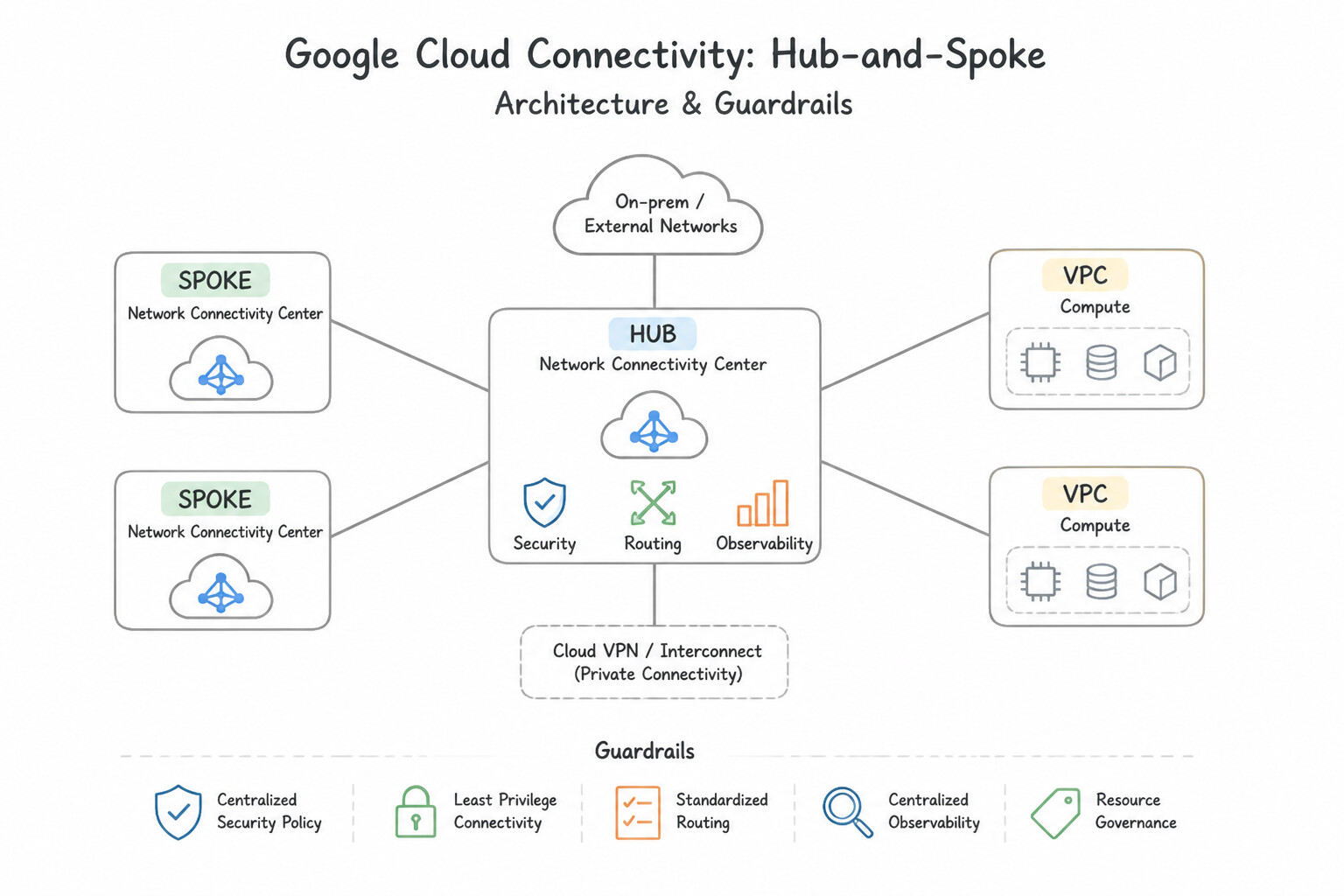
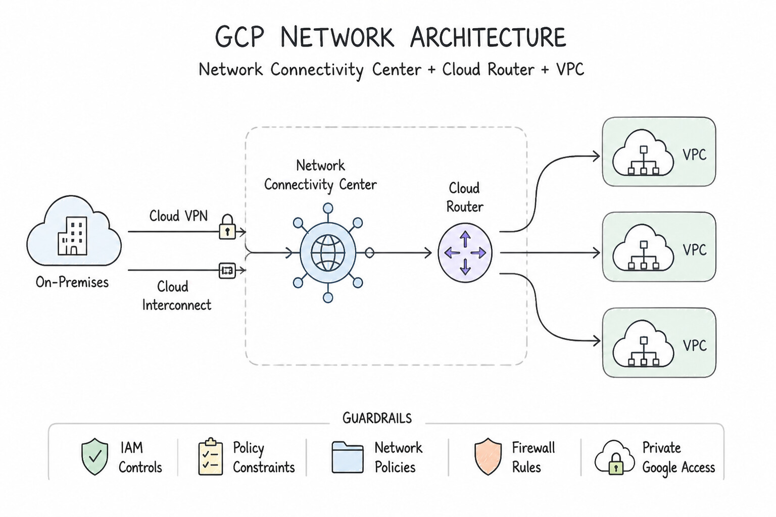
As organizations scale past 10–25 VPC networks and integrate managed producer services (like Cloud SQL or third-party SaaS via Private Services Access) alongside hybrid data centers, raw VPC Network Peering hits an architectural brick wall. Network Connectivity Center (NCC) replaces point-to-point peering chaos with a centralized Hub-and-Spoke control plane. However, engineers implementing NCC in Subsection 2.3 frequently stumble on four subtle mechanics:
- Spoke Type Confusion (
VPC Spokevs.Producer Spokevs.Hybrid Spoke—2.3a): IfWorkload-VPC-Auses Private Services Access (PSA) to connect to a Google-managed Cloud SQL tenant VPC, other VPC spokes in the NCC Hub cannot automatically reach that Cloud SQL instance—because the Cloud SQL VPC is peered withWorkload-VPC-A, not attached to the NCC Hub! To make PSA-peered services reachable across the entire NCC Hub, you must attach the peering connection as an NCC Producer Spoke. - Preset Topology Selection (
Meshvs.Star—2.3b): In aMeshtopology, every spoke belongs to thedefaultgroup and talks to every other spoke. When security compliance requires workload VPCs to be isolated from each other and only talk to central Shared-Services/Inspection VPCs, you must configure the NCC Hub with theSTARpreset topology (centergroup vs.edgegroup). - Overlapping Spokes & Missing PSC Propagation (
2.3c,2.3d): When an acquired subsidiary's VPC spoke has overlapping subnets, you must combine NCC CIDR Range Filters (--exclude-export-rangesso the overlapping prefix isn't advertised to the hub) with Private NAT. And when a central VPC spoke hosts Private Service Connect (PSC) endpoints, other VPC spokes cannot reach those PSC endpoints unless PSC Connection Propagation is enabled on the NCC Hub!
Consideration 2.3a: Differentiating spoke types
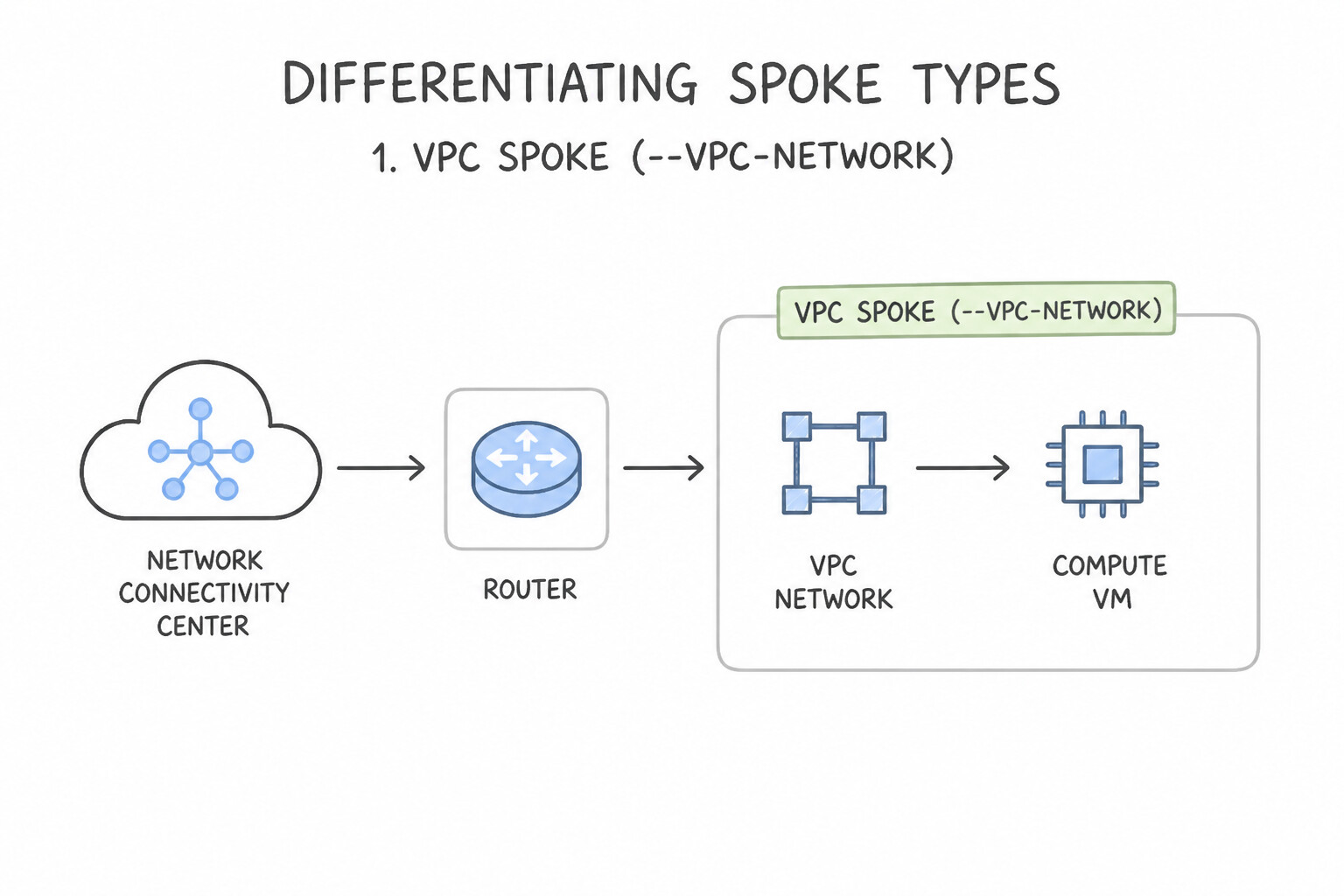
- 1. VPC Spoke (
--vpc-network): - Connects a standalone VPC or Shared VPC network to the NCC Hub so its subnet routes are exchanged across the hub's route table without using VPC Network Peering slots.
- Note: A VPC that is already peered via VPC Network Peering can be an NCC VPC spoke, except two VPCs cannot be connected to each other via both VPC Network Peering and the same NCC Hub simultaneously.
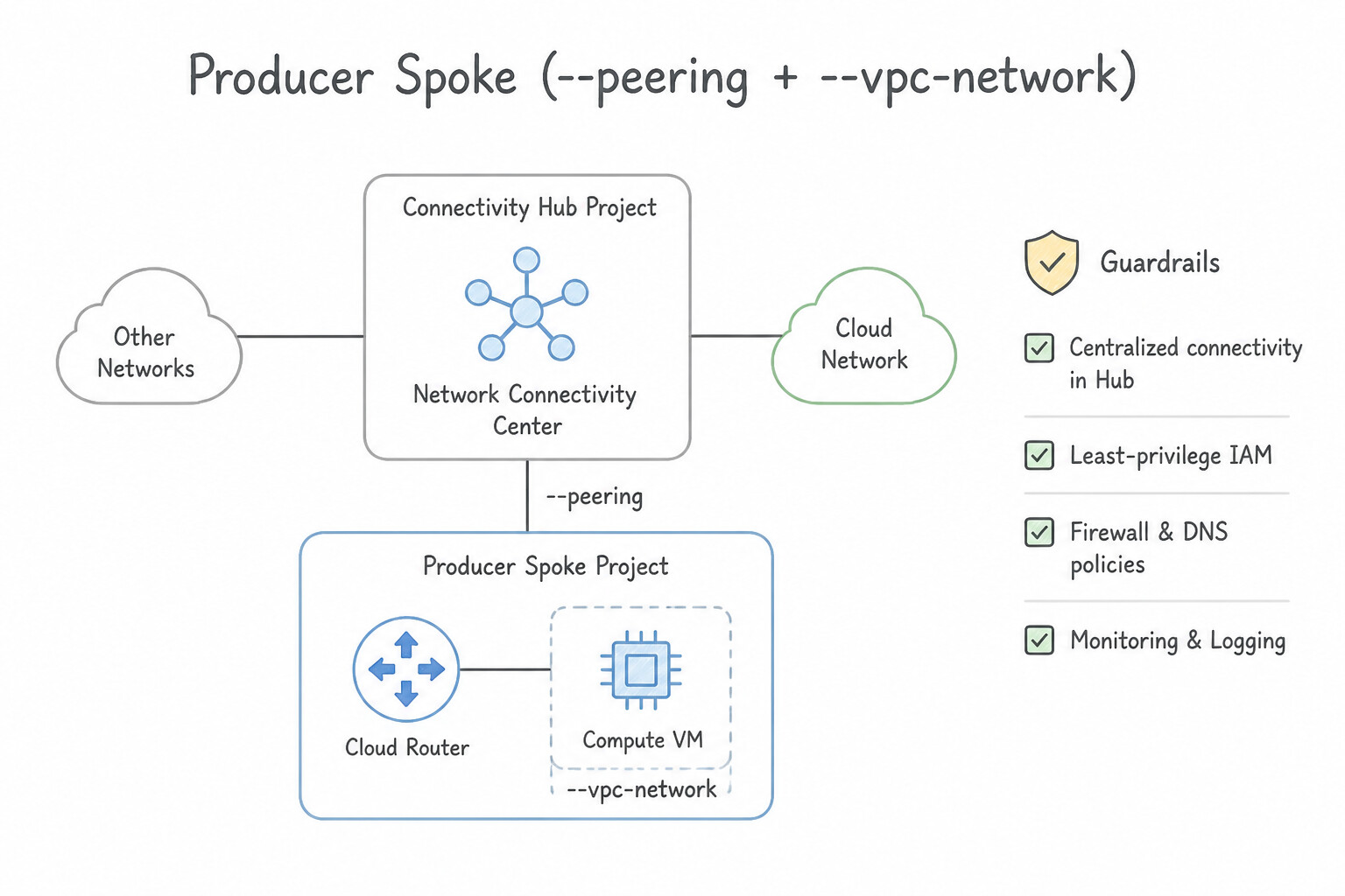
- 2. Producer Spoke (
--peering+--vpc-network): - Why it exists: Solves the non-transitivity of Private Services Access (
PSA)! WhenSpoke-VPC-1peers with a Google-managed producer network (like Cloud SQL, Memorystore, or NetApp Volumes) viaservicenetworking-googleapis-com, creating a Producer Spoke referencingSpoke-VPC-1and that peering name exports the producer's/16–/24subnet into the NCC Hub so all other VPC spokes and Hybrid spokes can reach the managed service! - 3. Hybrid Spoke (
--vpn-tunnel,--interconnect-attachment,--router-appliance): - Connects on-premises/multicloud environments (HA VPN, Dedicated/Partner/Cross-Cloud Interconnect VLAN attachments, or SD-WAN Router Appliance VMs) to the NCC Hub via Cloud Router BGP.
Key Implementation Patterns
- Integrating Third-Party SD-WAN Appliances: Use Create a Router appliance spoke and configure BGP peering with the Cloud Router. Router appliance spokes allow third-party NVAs to peer via BGP with the NCC Hub. (Avoid alternative: A VPC spoke connects entire networks, not specific router appliances.)
- Large-Scale VPC Mesh Connectivity: Use Create a Network Connectivity Center hub. Attach each VPC network as a VPC spoke. Network Connectivity Center using VPC spokes provides transitive connectivity between all attached VPCs efficiently. (Avoid alternative: VPC Peering requires a full mesh configuration which is difficult to manage at scale.)
- Encrypted Hybrid Connectivity: Use Create a VPN spoke and attach a High Availability (HA) VPN gateway. HA VPN spokes are the specific resource used to attach Cloud HA VPN gateways to an NCC Hub for encrypted hybrid connectivity. (Avoid alternative: Router appliance spokes are for third-party appliances (NVAs) hosted on VMs, not for managed Cloud VPN integration.)
Key Takeaways (2.3a)
- NCC uses a Hub and Spoke model to centralize network management.
- Spoke types must match the underlying resource (VPC, VPN, Interconnect, or Router Appliance).
- Router Appliance spokes are unique because they allow third-party VMs to participate in BGP routing with Cloud Router.
- VPC Network Peering is non-transitive and creates management overhead for full mesh topologies.
Consideration 2.3b: Managing topology (star, hub-spoke, mesh)
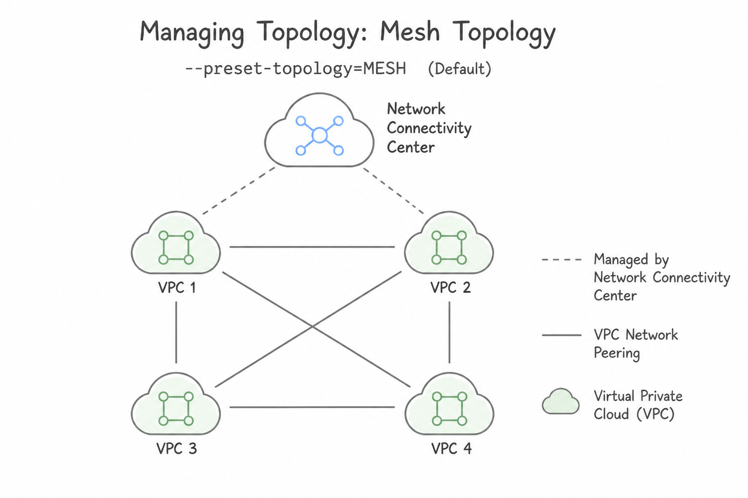
- Mesh Topology (
--preset-topology=MESH— Default): - All spokes are placed in a single
defaultspoke group with a single Hub Route Table. - Every VPC spoke has full-mesh Any-to-Any reachability with every other VPC spoke (and Hybrid/Producer spokes).
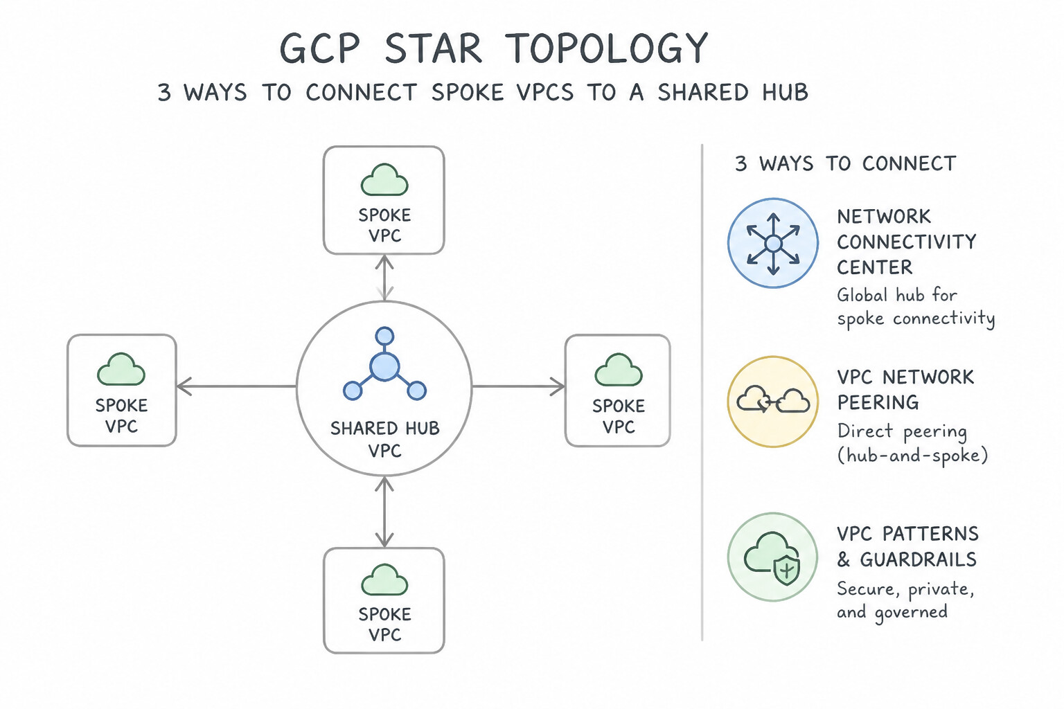
- Star Topology (
--preset-topology=STAR): - Creates two distinct spoke groups with separate route tables:
center(Core) Group: Holds shared services VPCs, central DNS/PSC hub VPCs, or Hybrid spokes. Center spokes can communicate with all Center spokes and all Edge spokes.edgeGroup: Holds isolated business-unit or tenant workload VPCs. Edge spokes can communicate only withcenterspokes—directedge-to-edgerouting is blocked at the NCC control plane!- Cross-Project Spoke Admin Approval (
Spoke State): When a project admin in a different project proposes a spoke to a centralized NCC Hub, the Hub Administrator must explicitly accept (accept-spoke) the spoke before its routes are injected into the Hub Route Table.
Key Implementation Patterns
- Scalable VPC Connectivity Beyond Peering Limits: Use Use Network Connectivity Center. Create a hub in the shared services project and attach the 100 VPCs as spokes. Network Connectivity Center enables a managed hub-and-spoke topology, simplifying connectivity for many VPCs.
- Integrating Third-Party SD-WAN Appliances: Use Create a Router appliance spoke and associate the SD-WAN VM instances with the hub. Router appliance spokes are specifically designed to integrate third-party NVAs, like SD-WAN routers, into the NCC hub using BGP. (Avoid alternative: VPC Network spokes connect entire networks, not specific virtual appliances running within them.)
Key Takeaways (2.3b)
- Network Connectivity Center (NCC) simplifies the management of complex network topologies.
- NCC uses a Hub-and-Spoke model to connect multiple VPCs.
- Standard VPC Peering is non-transitive and difficult to scale for large numbers of networks.
- NCC is the preferred solution for large-scale star or mesh requirements over manual peering or VPNs.
Consideration 2.3c: Configuring Private NAT and PSC propagation
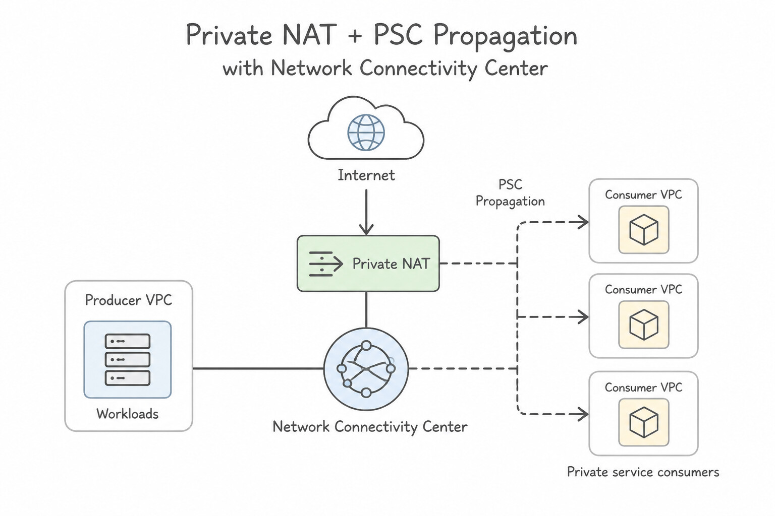
- Private NAT with Network Connectivity Center:
- Used when
Spoke-VPC-Ahas an overlapping CIDR (10.0.0.0/16) that conflicts withSpoke-VPC-Bor an on-premises Hybrid Spoke. - Configuration Steps:
- Configure
--exclude-export-ranges=10.0.0.0/16onSpoke-VPC-Aso the overlapping subnet is not advertised into the NCC Hub. - Create a non-overlapping subnet in
Spoke-VPC-Awith--purpose=PRIVATE_NAT(e.g.,192.168.100.0/24), which is automatically advertised to the NCC Hub. - Create a Cloud NAT gateway with
--type=PRIVATEand a NAT rule matchingnexthop.hub == "//networkconnectivity.googleapis.com/projects/.../hubs/HUB_NAME"to SNAT outbound traffic from10.0.0.0/16to the192.168.100.0/24Private NAT range! - Private Service Connect (
PSC) Connection Propagation (--export-psc): - Normally, a PSC Endpoint (
ForwardingRule) is only reachable inside the VPC where it was created (and from hybrid links attached to that VPC). - By enabling
--export-psc(PSC Connection Propagation) on the NCC Hub, a central Shared-Services VPC Spoke can create PSC Endpoints once, and NCC automatically propagates/32routes and NAT mappings for those PSC Endpoints into every other VPC Spoke in the NCC Hub (subject to Star/Mesh group visibility)!
Key Implementation Patterns
- Handling Overlapping CIDRs in NCC Spokes: Use Configure Private NAT in VPC-A and VPC-B to map their subnets to unique non-overlapping ranges advertised to VPC-C. Private NAT allows communication between VPCs with overlapping subnets by mapping them to unique ranges. (Avoid alternative: VPC Network Peering fails if the peered networks have overlapping IP address ranges.)
- Private NAT for Hybrid Connectivity: Use Configure a Private NAT gateway on the VPC network to perform Source Network Address Translation (SNAT) for traffic destined for the NCC Hub. Private NAT allows you to perform SNAT on traffic between private networks (like VPC to on-prem via NCC) to handle IP overlaps.
Key Takeaways (2.3c)
- VPC Peering does not support overlapping IP subnets.
- Network Connectivity Center (NCC) simplifies hub-and-spoke network management.
- Private NAT (Inter-VPC NAT) is the standard solution for allowing communication between VPCs with overlapping CIDR ranges without re-addressing.
- Network Connectivity Center (NCC) connects heterogeneous networks using a Hub and Spoke model.
Consideration 2.3d: Configuring CIDR filters
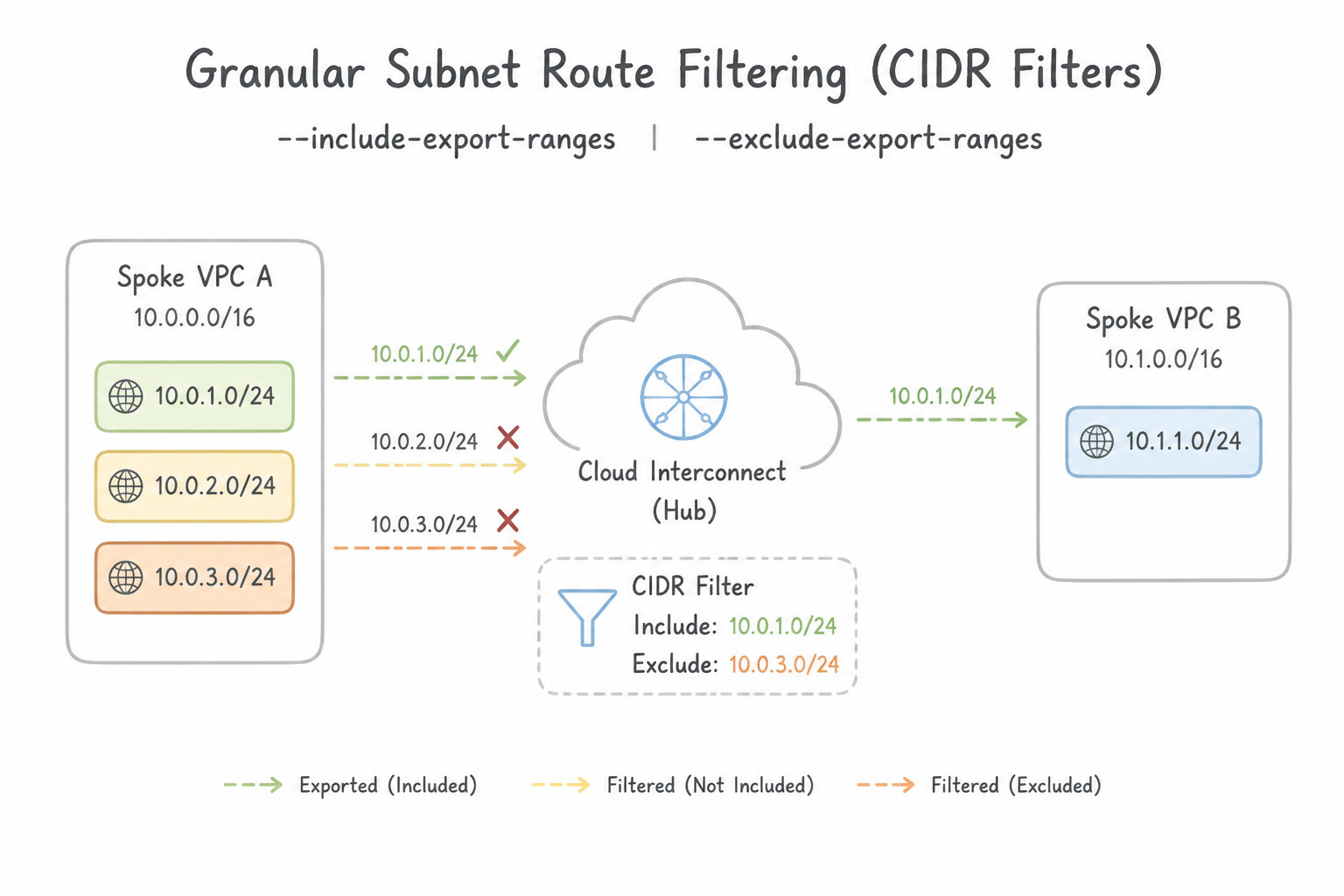
- Granular Subnet Route Filtering (
--include-export-ranges&--exclude-export-ranges): - By default, attaching a VPC Spoke exports all IPv4 subnet ranges in that VPC to the NCC Hub.
- Use
--exclude-export-rangesto prevent local-only subnets (such as GKE Pod ranges, workbench scratch subnets, or overlapping10.0.0.0/16ranges) from being advertised to the rest of the enterprise. - Use
--include-export-rangeswhen you want an allowlist-only model where only explicitly listed CIDRs from that VPC Spoke are exported to the NCC Hub. - Note: You can update
--include-export-rangesand--exclude-export-rangesdynamically on existing VPC spokes without recreating the spoke!
Key Implementation Patterns
- Excluding Sensitive Subnets in VPC Spokes: Use Create the VPC spoke with an export filter that excludes the 10.10.1.0/24 CIDR range. Use the exclude export ranges feature on the VPC spoke to prevent specific subnet CIDRs from being advertised to the NCC Hub. (Avoid alternative: Disabling all route exports would disconnect the Frontend subnet, which needs to remain accessible.)
- Filtering BGP Routes on Router Appliance Spokes: Use Configure a BGP route policy on the Cloud Router to accept only the 10.50.0.0/16 prefix. Use a Cloud Router BGP inbound route policy to filter received prefixes and accept only the specific IP address range required. (Avoid alternative: Firewall rules filter data traffic, not BGP routing updates; they will not stop the route from being learned.)
- Preventing Transitive Routing Loops with Hybrid Spokes: Use Create a BGP route policy that matches the on-premises CIDR ranges. Set the Multi-Exit Discriminator (MED) to a higher value. Apply this policy to the inbound BGP session. Apply an inbound BGP route policy on the VPN Cloud Router to set a higher MED for on-premises CIDRs, making the VPN path less preferred for egress traffic.
Key Takeaways (2.3d)
- NCC VPC spokes export all local subnet routes to the Hub by default.
- Use export filters (include/exclude ranges) on the spoke to control which subnets are advertised.
- Routing visibility is distinct from firewall rules; use route filtering to isolate network segments at the topology level.
- Network Connectivity Center uses Cloud Router to manage BGP sessions for Router Appliance spokes.
Consideration 2.3e: Monitoring and troubleshooting NCC
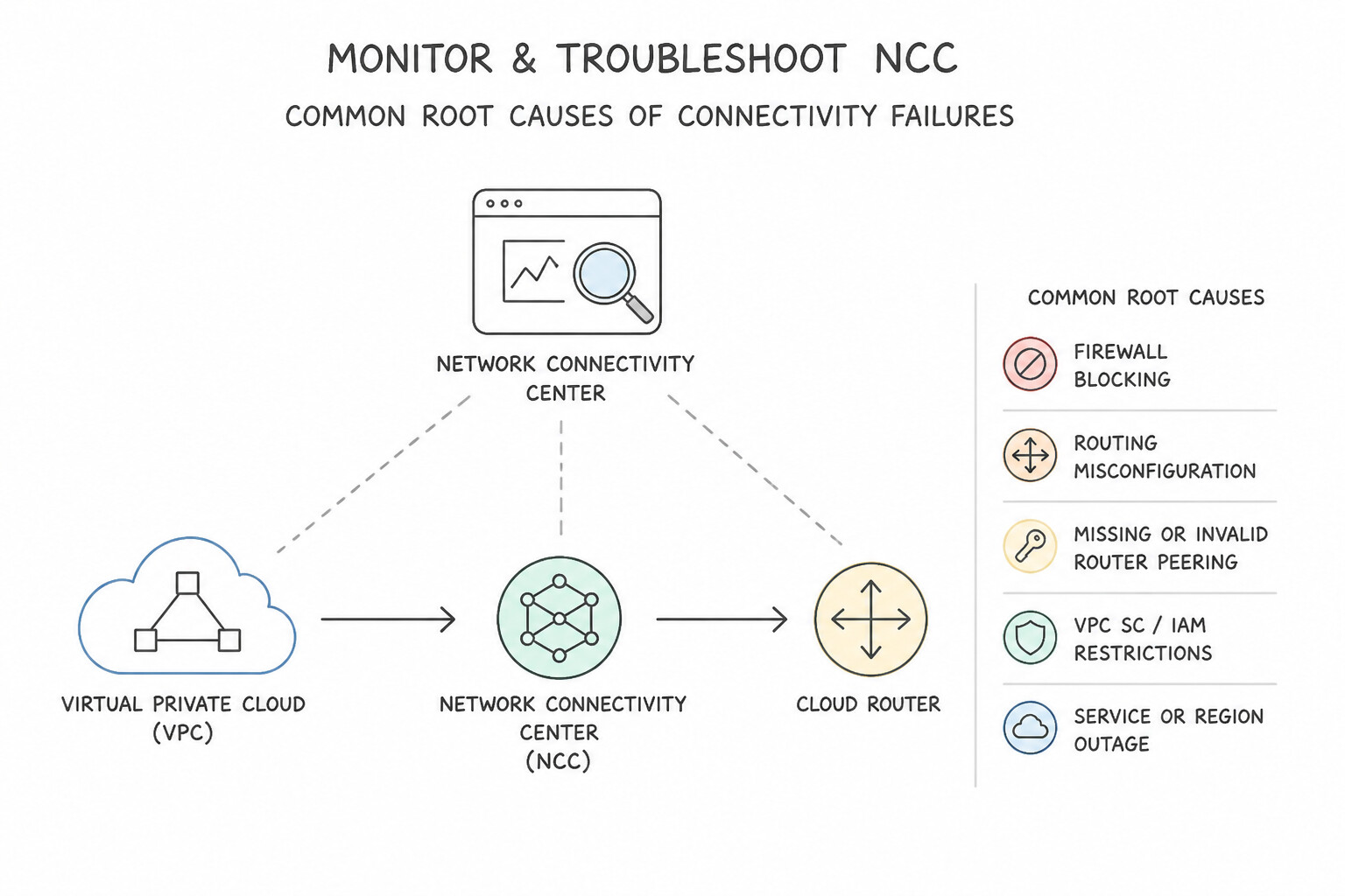
- Common Root Causes of NCC Connectivity Failures:
- Dynamic Routing Mode is
REGIONALInstead ofGLOBAL: When a Hybrid Spoke inus-east1connects to an NCC Hub, VPC Spokes inus-west1will not receive those hybrid routes unless the VPC hosting the Hybrid Spoke's Cloud Router hasGLOBALdynamic routing mode enabled! - Spoke State is
PENDINGorINACTIVE: Cross-project spokes await Hub Admin approval (gcloud network-connectivity hubs accept-spoke). - VPC Firewall Rules / NGFW Policies: Remember that NCC only programs routes in the Hub Route Table; it does not automatically open ingress firewall rules on target VPC spokes! You must still allow the source spoke's CIDR (or Secure Tag) in the destination VPC's firewall policy.
- Route Quota Exhaustion: Monitor NCC Hub route table usage metrics in Cloud Monitoring (
networkconnectivity.googleapis.com/hub/route_table/routes_count) and Network Analyzer alerts.
Key Implementation Patterns
- Diagnosing Router Appliance Spoke BGP Sessions: Use Navigate to the Cloud Router page in the Google Cloud console and view the BGP session status. Router Appliance spokes rely on Cloud Router for BGP peering; the Cloud Router page displays the real-time status of these BGP sessions.
- Visualizing NCC Topology: Use Open Network Topology in the Network Intelligence Center and select the specific Hub context. Network Topology provides an automatic visual graph of your network infrastructure, including NCC Hub and Spoke relationships. (Avoid alternative: Cloud Monitoring tracks performance metrics but does not visualize network topology or hierarchy.)
- Troubleshooting Transitive Routing Connectivity: Use Create a Connectivity Test in Network Intelligence Center specifying the source and destination IP addresses. Connectivity Tests simulate the network path and analyze configuration (routes, firewalls, NCC) to identify exactly where and why traffic is dropping.
Key Takeaways (2.3e)
- Router Appliance spokes in NCC use Cloud Router to establish BGP sessions.
- To troubleshoot BGP or route exchange issues, always check the Cloud Router details page.
- VM status indicates infrastructure health, while Cloud Router status indicates network protocol health.
- Network Connectivity Center (NCC) uses a Hub-and-Spoke model to manage global connectivity.
Quick Decision Cheat Sheet (Subsection 2.3)
If the Scenario Requires... | Choose This Google Cloud Pattern | Avoid This Common Mistake |
|---|---|---|
"Share a Private Services Access ( PSA) Cloud SQL / Memorystore subnet across all spokes in an NCC Hub" | Create an NCC Producer Spoke referencing the servicenetworking-googleapis-com peering | Enabling --export-custom-routes on native VPC Peering alone |
"Isolate edge workload VPCs from each other while allowing access to central hub VPCs in NCC" | Star Topology ( STAR) with center and edge spoke groups | Mesh Topology ( MESH) |
"Prevent a specific GKE Pod range or private subnet in a VPC Spoke from being advertised to the NCC Hub" | Configure --exclude-export-ranges on the NCC VPC Spoke | Deleting the subnet route or adding a deny firewall rule (doesn't stop CIDR overlap in the Hub route table) |
"Share Private Service Connect ( PSC) endpoints across multiple VPC Spokes in an NCC Hub" | Enable PSC Connection Propagation ( --export-psc) on the NCC Hub | Configuring DNS Peering alone (DNS resolves the IP, but without PSC propagation the /32 route is missing in other spokes!) |
"Cross-project VPC Spoke is created by a project admin, but routes do not appear in the NCC Hub" | Have the Hub Admin run gcloud network-connectivity hubs accept-spoke to activate the PENDING spoke | Restarting VMs or recreating the NCC Hub |
Further Reading (Subsection 2.3)
- Network Connectivity Center overview — Provides a high-level overview of NCC, the Hub, and the different Spoke types available for configuration.
- Router appliance overview — Specifically details how Router appliance spokes work, including the requirement for Cloud Router and BGP peering.
- VPC spokes overview — Explains specifically how VPC spokes allow VPC networks to connect for transitive reachability.
- Work with hubs and spokes — Detailed instructions and requirements for creating HA VPN spokes to connect on-premises networks.
- Private Service Connect connection propagation through NCC — Explains how Private NAT enables communication between VPC networks that have overlapping IP address ranges by using Network Address Translation.
- VPC spokes overview — Refer to the section 'Create a VPC spoke' and specifically the details regarding the '--exclude-export-ranges' flag to understand how to filter advertised subnets.
Book TOC · Previous · Chapter 2 of 8 · Next
AwesomeGCP.com Learning
The approach taken is a question-led learning approach: you explore realistic project scenarios where you need to make decisions or take actions to achieve business goals within specific constraints. Instead of passive learning, you are challenged to think and work through the options to master the Professional Cloud Network Engineer (PCNE) certification!