Book TOC · Previous · Chapter 1 of 8 · Next
Chapter 1: Enterprise Network Architecture, VPC Topology, IPAM Strategy & Multi-Cloud Design
Chapter Focus: HA/DR network topologies, DNS architecture, Global vs. Regional Load Balancer selection, RFC 1918/non-RFC 1918 IPAM, Shared VPC vs. Peering vs. NCC vs. PSC, and hybrid connectivity design.
Subsection 1.1: Designing an overall network architecture
The Big Picture
When organizations lift-and-shift data center habits into Google Cloud, they typically make three architectural blunders on day one: they select Standard Network Service Tier to save a few cents per gigabyte (unknowingly breaking global Anycast load balancing and pushing inter-continental user traffic onto the public ISP internet), they grant project developers broad roles/compute.networkAdmin permissions instead of isolating network governance in a Shared VPC Host Project, and they connect to managed services like Cloud SQL, Vertex AI, and third-party SaaS using brittle transitive peering hacks instead of Private Service Connect (PSC).
As the footprint grows across regions and business units, these shortcuts trigger cascading failures: GKE clusters exhaust their secondary /24 Pod ranges mid-incident, VPC quota ceilings block autoscaling Managed Instance Groups, and regional outages take down applications that were assumed to be "globally redundant" because their DNS records lacked health-checked routing policies. Subsection 1.1 tests your ability to make the high-level architectural choices—across Network Tiers, High Availability & DR, DNS Topology, Load Balancing, GKE Capacity, Shared VPC IAM, Managed Service Connectivity, and Quotas—before a single subnet is provisioned.
Consideration 1.1a: Designing for high availability, failover, disaster recovery, and scale
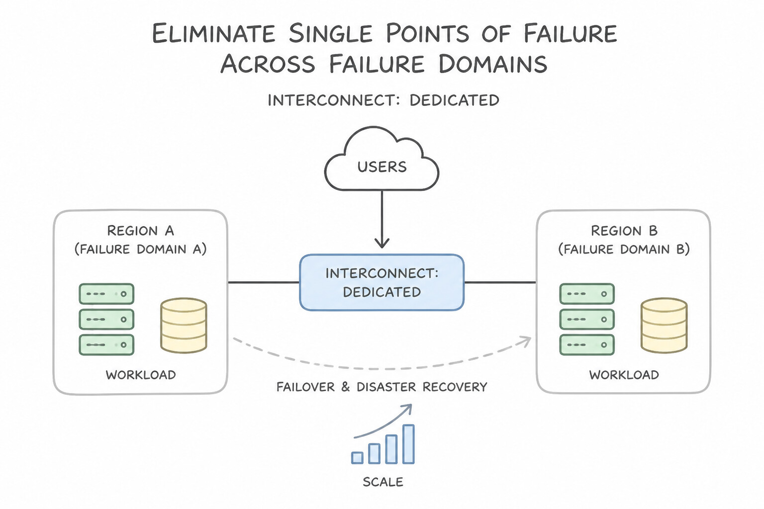
When evaluating scenarios on resilient network architectures:
- Eliminate Single Points of Failure Across Failure Domains: Distribute Compute Engine instances and GKE nodes across multiple zones within a region to survive zonal failures, and across multiple regions behind a Global External Application Load Balancer (or Cloud DNS Routing Policies for regional stacks) to survive full regional outages.
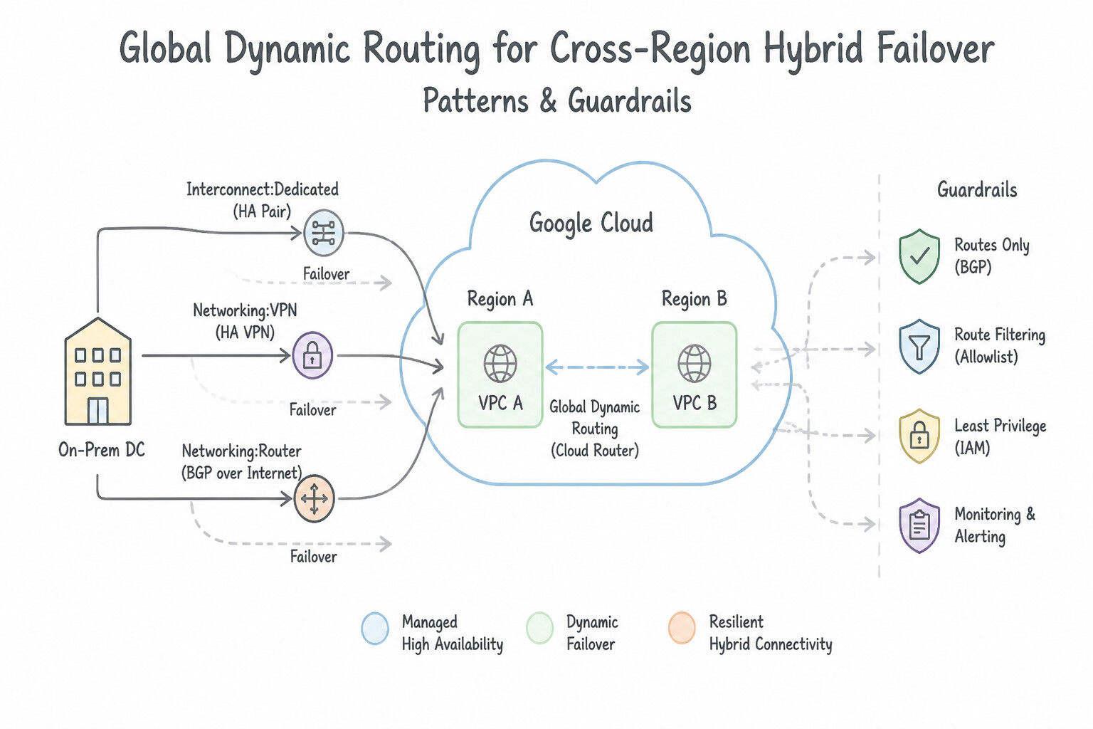
- Global Dynamic Routing for Cross-Region Hybrid Failover: By default, a VPC uses
REGIONALdynamic routing mode, meaning a Cloud Router inus-central1only advertisesus-central1subnets and only installs learned on-premises routes inus-central1. Always switch the VPC toGLOBALdynamic routing mode so hybrid links in Region A automatically provide backup reachability for workloads in Region B. - Stateless vs. Stateful Failover: Pair global Anycast L7 load balancing (which automatically drains unhealthy regional Managed Instance Groups in seconds based on health check failures) with cross-region database replication (e.g., Cloud SQL HA with cross-region read replicas or Cloud Spanner multi-region).
- Quota & Scale Planning: Before scaling into a disaster recovery region, audit regional and per-VPC quotas (such as static/dynamic route limits, VPC peering limits, forwarding rules, and in-use IP addresses) so failover autoscaling is never blocked by quota exhaustion.
Key Implementation Patterns
- 99.99% Availability with Dedicated Interconnect: Use Order four connections across two metropolitan areas. Ensure each metropolitan area has two connections in different edge availability domains. The 99.99% SLA requires four connections total: two connections in each of two separate metropolitan areas.
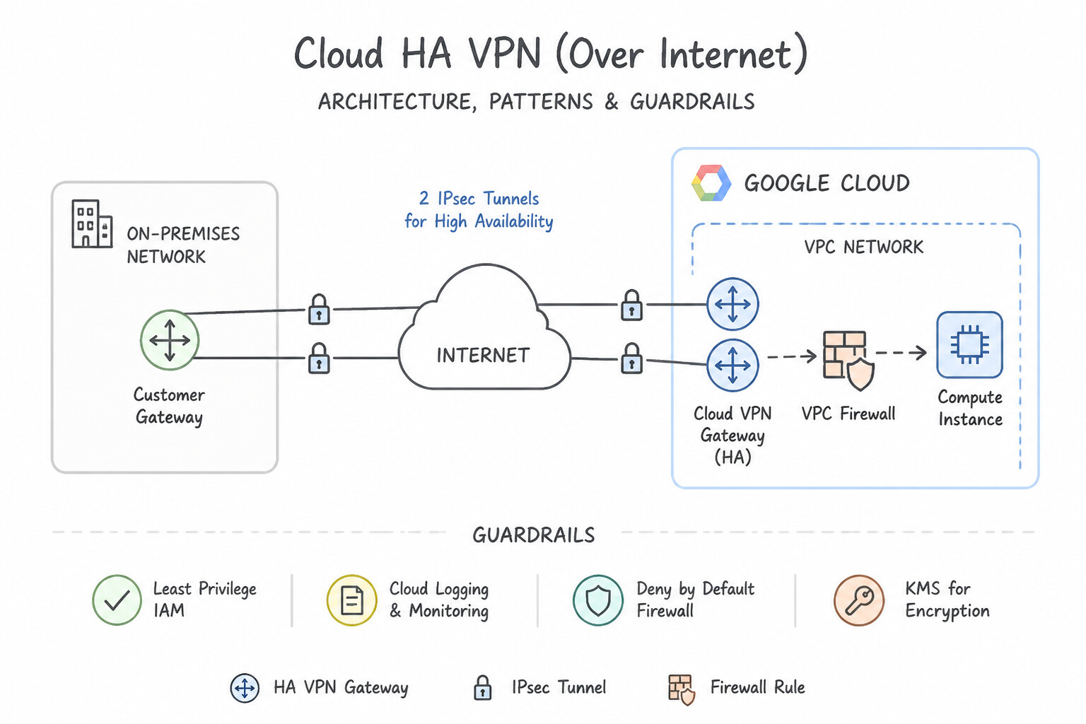
- HA VPN with BGP for Failover: Use Create an HA VPN gateway with two tunnels. Configure Border Gateway Protocol (BGP) sessions for dynamic routing. HA VPN requires two tunnels and BGP dynamic routing to provide a 99.99% SLA and automatic failover. (Avoid alternative: Static routes do not automatically handle failover as seamlessly as BGP, which is required for the standard HA VPN setup.)
Key Takeaways (1.1a)
- The 99.99% SLA for Dedicated Interconnect requires four physical connections.
- Connections for 99.99% SLA must be distributed across two different metropolitan areas.
- Each metropolitan area must have two connections in distinct edge availability domains.
- The 99.9% SLA only requires two connections in a single metropolitan area.
Consideration 1.1b: Designing the DNS topology (on-premises, Cloud DNS)
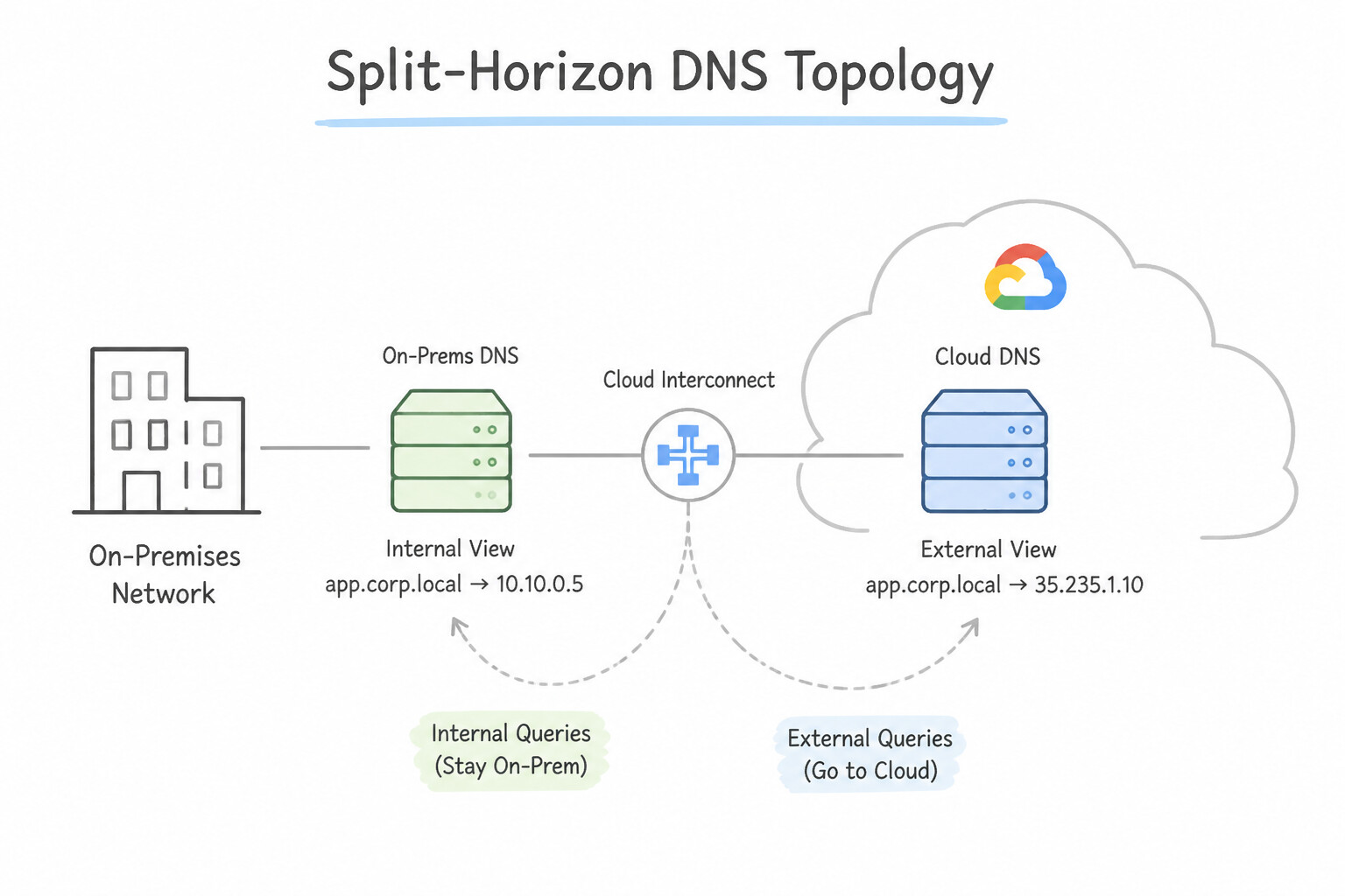
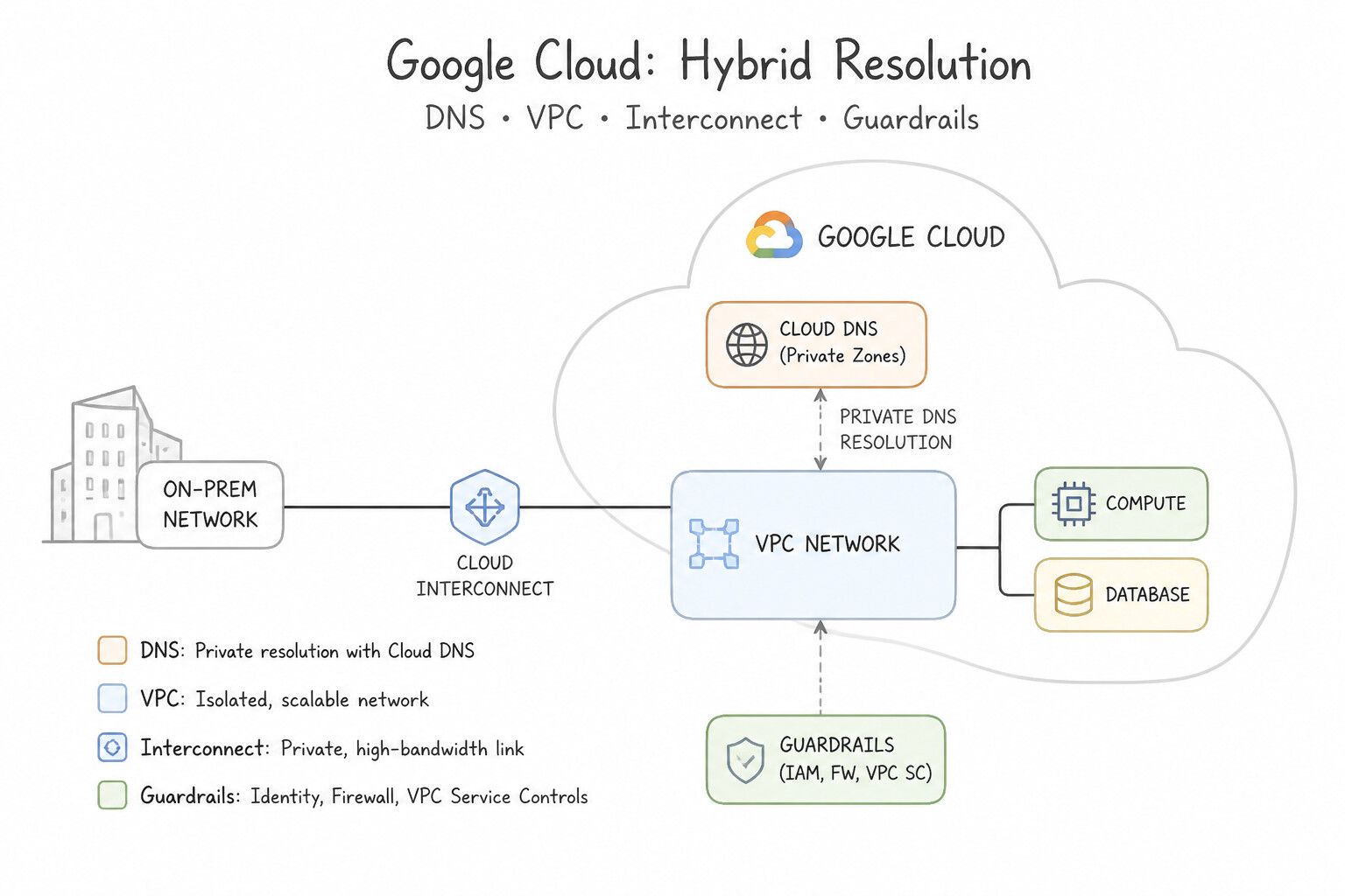
When architecting DNS resolution across Google Cloud and hybrid environments:
- Split-Horizon DNS: Create a Cloud DNS Public Zone and a Cloud DNS Private Zone with the exact same domain name (e.g.,
api.example.com.). Authorized VPCs automatically resolve the Private Zone's internal RFC 1918 records (10.x.x.x), while external internet clients resolve the Public Zone's external Load Balancer VIPs. - Hybrid Resolution Directions:
- GCP → On-Premises: Create a Cloud DNS Private Forwarding Zone targeting on-premises DNS server IPs (queries exit via
35.199.192.0/19over HA VPN / Interconnect). - On-Premises → GCP: Enable a Cloud DNS Inbound Server Policy on the VPC, which assigns a regional internal IP from each subnet so on-premises resolvers can forward
.internalor private zone queries into Cloud DNS. - Multi-VPC DNS Sharing: Prefer Cross-Project Binding (attaching a single Private Zone to multiple VPCs across projects in a Shared VPC or standalone model) or DNS Peering (delegating a namespace from a consumer VPC to a producer VPC) rather than duplicating private zones across every project.
Key Implementation Patterns
- Split-Horizon DNS Architecture: Use Create a public Cloud DNS zone for example.com with the public IP address. Create a private Cloud DNS zone for example.com attached to the VPC network with the private IP address. Split-horizon DNS uses a private zone for VPC traffic and a public zone for internet traffic for the same domain.
- Hybrid DNS: Outbound Forwarding: Use Create a private Cloud DNS forwarding zone for legacy.local. Configure the zone to target the on-premises DNS server IP addresses. A forwarding zone delegates DNS queries for a specific domain to target name servers, such as those located on-premises.
- Hybrid DNS: Inbound Forwarding: Use Create an inbound server policy in Cloud DNS. Configure the on-premises DNS servers to forward queries to the inbound forwarding IP addresses. An inbound server policy provides entry point IP addresses that on-premises DNS servers can use to resolve internal Google Cloud hostnames.
Key Takeaways (1.1b)
- Split-Horizon DNS: Use separate public and private managed zones for the same domain to serve different data to internal and external users.
- Private Zones: These are visible only to the VPC networks you specify and take precedence over public zones for queries originating from those VPCs.
- Resolution Order: Google Cloud resolves queries in the order of Private Zone -> Public Zone -> Public Internet.
- Use Cloud DNS Forwarding Zones for outbound resolution (resolving on-premises hostnames from Google Cloud).
Consideration 1.1c: Choosing a load balancer for an application or solution
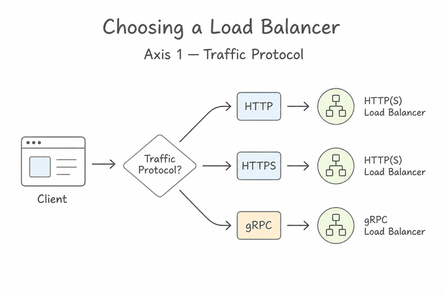
Use this 4-axis decision tree to select the exact load balancer in Production:
- Axis 1 — Traffic Protocol (
HTTP/HTTPS/gRPCvs.TCP/SSL/UDP/ESP/All-Ports): - Layer 7 HTTP(S) features (URL maps, host/path routing, Cloud CDN, Cloud Armor WAF, Identity-Aware Proxy) require an Application Load Balancer (
ALB). - Non-HTTP traffic requires a Network Load Balancer (Proxy Network LB for TCP/SSL connection termination; Passthrough Network LB for ultra-low-latency direct server return [DSR], UDP, ESP, ICMP, or preserving the client's raw source IP packet header).
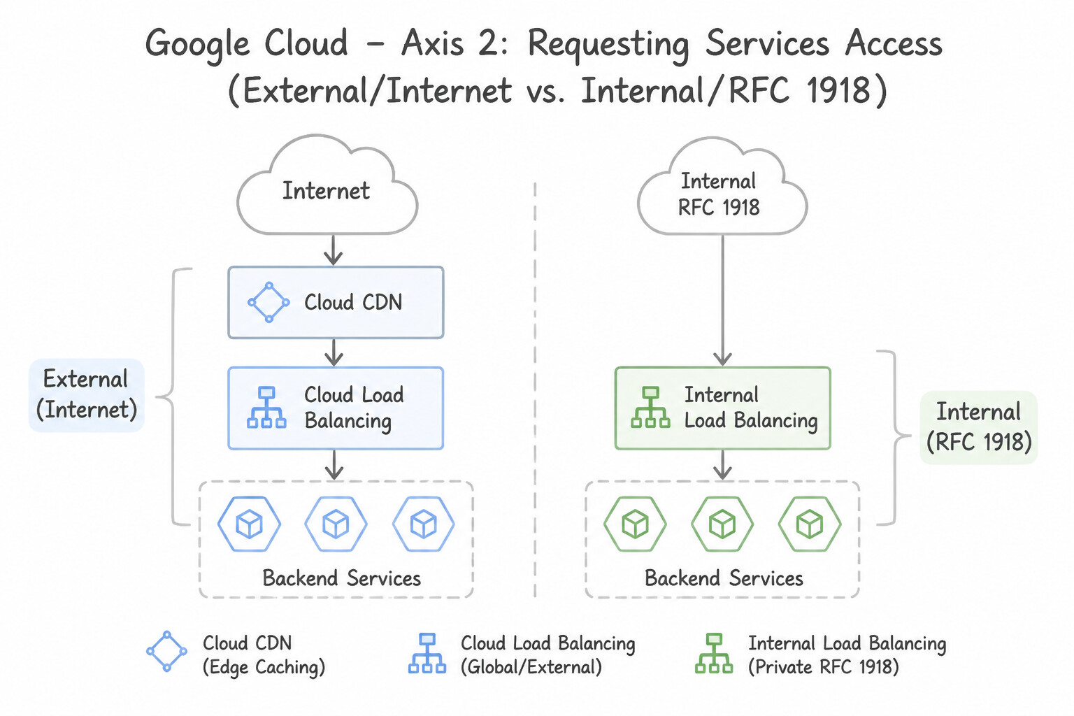
- Axis 2 — Client Access (
External / Internetvs.Internal / RFC 1918): - Public internet users hit External load balancers; VPC-internal and hybrid VPN/Interconnect clients hit Internal load balancers.
- Axis 3 — Geographic Scope (
Globalvs.Regional): - Need a single global Anycast IP routing users to the closest healthy region across
us,europe, andasia? Choose Global External ALB or Global External Proxy Network LB (requires Premium Tier). - Have strict data sovereignty / regulatory compliance requiring TLS termination and traffic processing to stay strictly inside one jurisdiction, or using Standard Tier? Choose a Regional External ALB or Regional Network LB.
- Axis 4 — Internal Cross-Region HA: Use Cross-Region Internal ALB for active-active/active-passive L7 internal microservice failover across regions, or enable Global Access on a Regional Internal Passthrough NLB so clients in any region or on-premises can reach it.
Key Implementation Patterns
- Global Content Delivery with Caching: Use Configure a Global External Application Load Balancer. The Global External Application Load Balancer handles Layer 7 traffic globally and supports Cloud CDN integration. (Avoid alternative: Network Load Balancers operate at Layer 4 and do not support HTTP-based features like Cloud CDN.)
- High-Performance UDP Traffic: Use Configure an external passthrough Network Load Balancer to distribute the UDP traffic. External passthrough Network Load Balancers support UDP, offer low latency, and preserve the client source IP address. (Avoid alternative: Application Load Balancers support HTTP/S, not UDP, and do not preserve the client IP address in the packet header.)
Key Takeaways (1.1c)
- Cloud CDN requires an Application Load Balancer (HTTP/S) because it relies on Layer 7 web standards.
- Use Global External Application Load Balancers for applications that serve users worldwide via a single IP address.
- Network Load Balancers operate at Layer 4 and are not suitable for HTTP-specific features like caching or URL-based routing.
- External passthrough Network Load Balancers are Layer 4 regional load balancers.
Consideration 1.1d: Designing for hybrid connectivity including Private Google Access
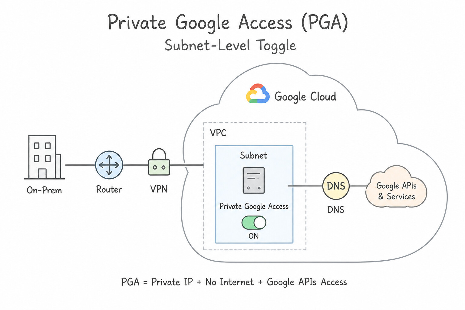
When connecting private VMs and on-premises hosts to Google APIs without traversing the public internet:
- Private Google Access (
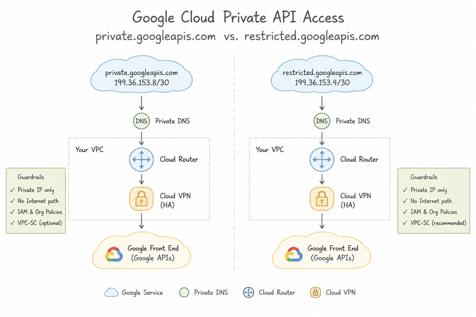
PGA) is a Subnet-Level Toggle: Enabling PGA on a VPC subnet allows VMs without external IP addresses in that subnet to reach Google APIs and services. private.googleapis.com(199.36.153.8/30) vs.restricted.googleapis.com(199.36.153.4/30):- Use
199.36.153.8/30(private.googleapis.com) for standard private access to almost all Google APIs. - Use
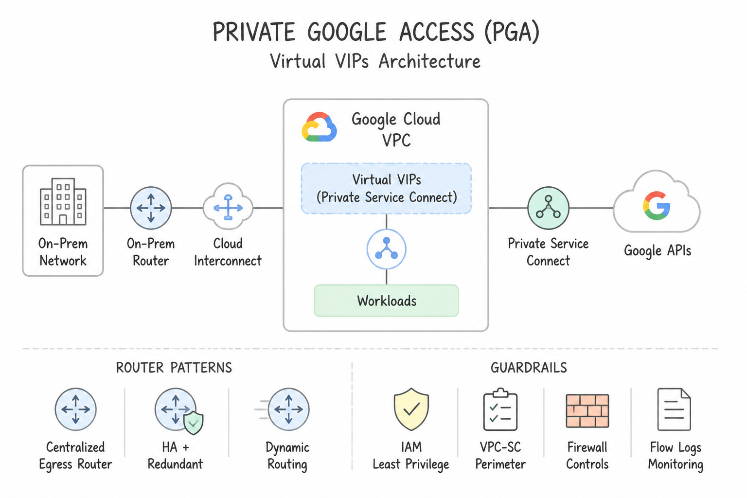
199.36.153.4/30(restricted.googleapis.com) when your organization enforces VPC Service Controls (VPC-SC)—this VIP strictly supports only VPC-SC compliant services and blocks non-compliant APIs that could be used as data exfiltration channels (such as consumer Gmail or unmanaged endpoints). - Extending Private Google APIs to On-Premises Hosts: On-premises hosts cannot use Google's default internet route. To give on-premises servers private access to Google APIs over Cloud Interconnect or HA VPN:
- Configure Cloud Router Custom Route Advertisement to announce
199.36.153.8/30(or199.36.153.4/30) over BGP to on-premises routers, OR create a Private Service Connect (PSC) endpoint for Google APIs (which assigns an internal IP from your VPC or a198.18.x.xIP) and advertise that IP via BGP. - Configure on-premises DNS (or a Cloud DNS Private Zone + Inbound Server Policy) to map
*.googleapis.comvia CNAME toprivate.googleapis.com.orrestricted.googleapis.com..
Key Implementation Patterns
- Private Google Access for On-Premises Hosts: Use Configure on-premises DNS to resolve *.googleapis.com to private.googleapis.com. Advertise the 199.36.153.8/30 IP address range via Cloud Router. You must direct API traffic to the specific private VIPs via DNS CNAMEs and ensure the route to those VIPs is advertised over the VPN.
- Restricted VIP for Compliance: Use Configure on-premises DNS to resolve *.googleapis.com as a CNAME to restricted.googleapis.com and map it to the IP address range 199.36.153.4/30. Restricted VIP (199.36.153.4/30) limits access only to APIs supported by VPC Service Controls, ensuring compliance with the security policy.
- Cloud Router Custom Route Advertisement: Use Add a custom route advertisement for 199.36.153.8/30 on the Cloud Router BGP session. Cloud Router does not advertise Google API VIPs by default; you must add a custom route advertisement. (Avoid alternative: Cloud NAT handles outbound internet access for VMs, not route propagation to on-premises networks.)
Key Takeaways (1.1d)
- Google APIs are public by default; private access requires specific DNS and routing changes.
- Private Google Access (subnet level) is for GCP VMs; Private Google Access for on-premises hosts is for hybrid connections.
private.googleapis.comuses the199.36.153.8/30IP range.- Cloud Router must advertise the Google API VIP range to the on-premises network.
Consideration 1.1e: Planning GKE networking including secondary ranges and control plane access
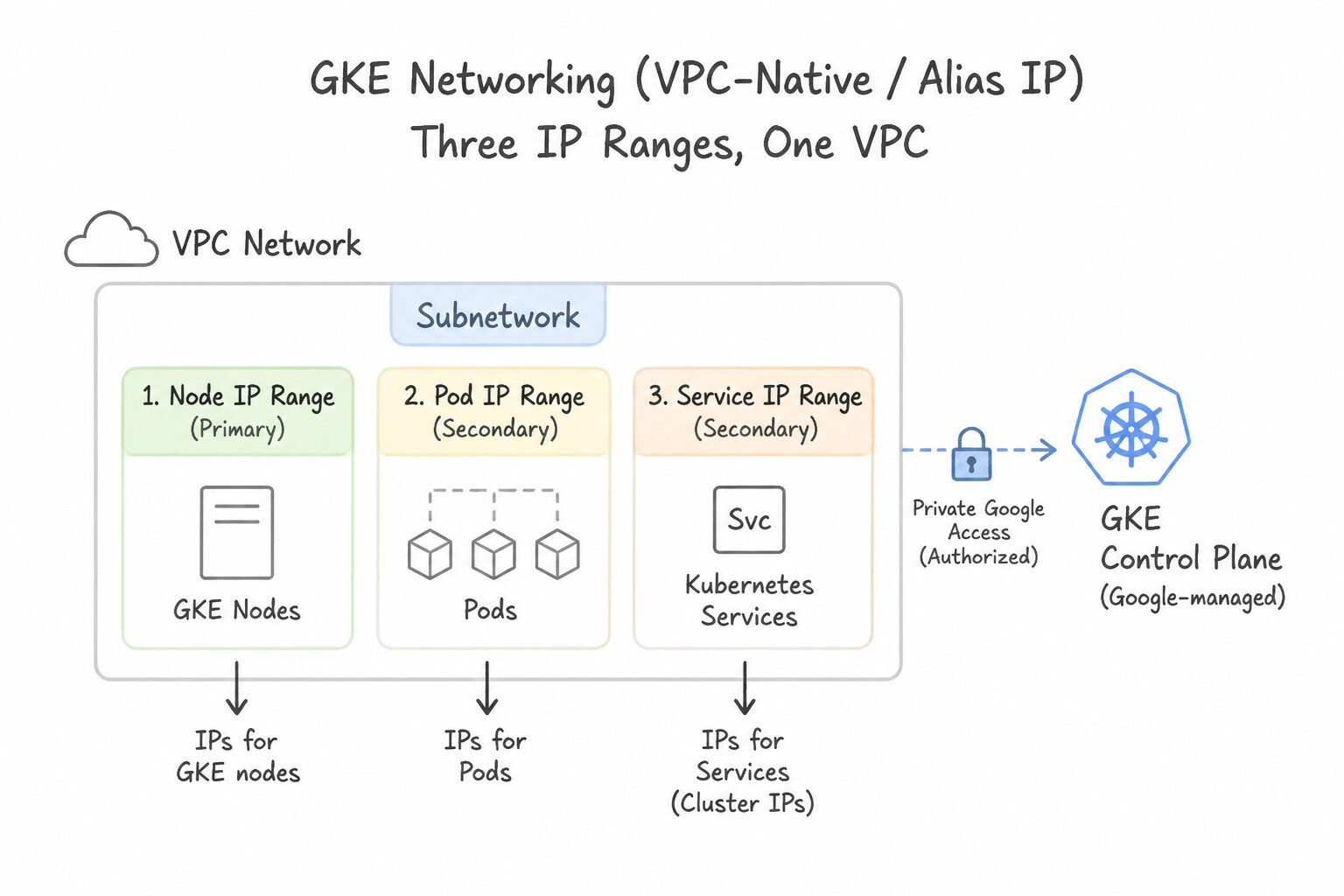
GKE networking capacity planning is one of the most critical calculation topics in production:
- Three Distinct IP Ranges in VPC-Native (
Alias IP) Clusters: - Primary Subnet Range (Nodes): Provides internal IPs for GKE worker node VMs (
1 IP per node+4 reserved IPs per subnet). - Secondary Subnet Range 1 (Pods): Allocates a dedicated alias IP block to each node based on
--max-pods-per-node. - Secondary Subnet Range 2 (Services /
ClusterIP): Virtual IPs internal to the cluster (or managed by GKE). - The Mandatory
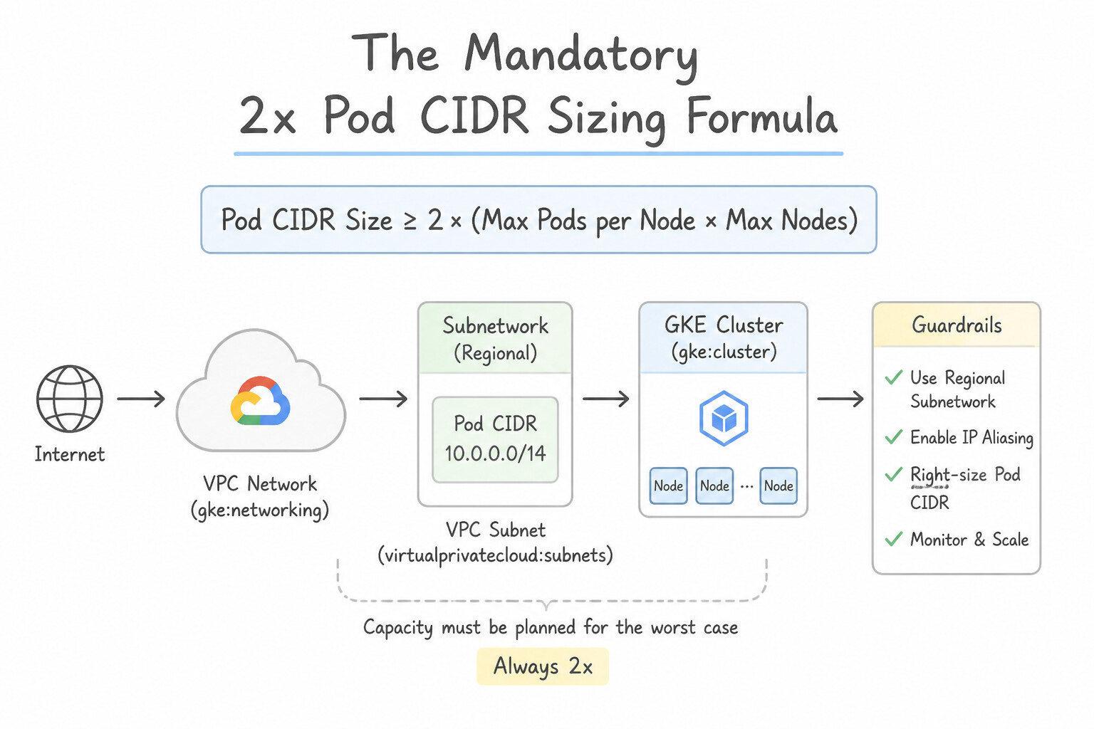
2xPod CIDR Sizing Formula: GKE allocates a fixed subnet mask to each node equal to twice the--max-pods-per-nodesetting (to allow Pod churn during rolling upgrades): - Default
110max Pods/node → $110 \times 2 = 220$ IPs → rounds up to a/24(256 IPs) per node! Thus a/21Pod secondary range ($2^{32-21} = 2,048IPs) supports at most @@ESCAPEDDOLLAR@@2,048 / 256 = 8 nodes at default settings! - To conserve IP space when nodes run fewer Pods, lower
--max-pods-per-node(e.g.,32Pods/node → $64$ IPs →/26per node, allowing 32 nodes inside the same/21Pod range;8Pods/node →/28(16 IPs) per node). - GKE Control Plane Endpoint Access: Plan whether CI/CD runners and administrators will reach the
kube-apiservervia a DNS-based endpoint (recommended for dynamic global IAM/authorized access), a Private IP endpoint only (reachable over VPC/VPN/Interconnect with Control Plane Global Access enabled), or a restricted public endpoint locked down with Control Plane Authorized Networks.
Key Implementation Patterns
- Pod CIDR Capacity Planning: Use Configure the secondary IP address range with a /17 CIDR block. A /17 range provides 32,768 IPs, which covers the 25,600 IPs needed (100 nodes 256 IPs/node). (Avoid alternative: A /24 range provides 256 IPs, which covers only 1 node, not 100.)*
- Securing Public Control Planes: Use Enable Master Authorized Networks on the cluster. Add the CI/CD system's IP address ranges to the list of authorized networks. Master Authorized Networks restricts access to the GKE public control plane endpoint to only specific IP address ranges.
- Private Cluster & Interconnect Access: Use Create a private cluster. Enable control plane access using the private endpoint. Disable control plane access using the public endpoint. A private cluster removes public IPs from nodes. Enabling the private endpoint and disabling the public endpoint restricts master access to the private network only.
Key Takeaways (1.1e)
- VPC-native GKE clusters use secondary subnet ranges for Pod IP addresses.
- By default, each GKE node is assigned a /24 CIDR block (256 IPs) to support up to 110 pods.
- Cluster capacity planning requires multiplying the maximum number of nodes by the per-node CIDR size (256) to determine the necessary secondary range size.
- The GKE control plane resides in a Google-managed network, distinct from the customer VPC.
Consideration 1.1f: Planning IAM roles including Shared VPC
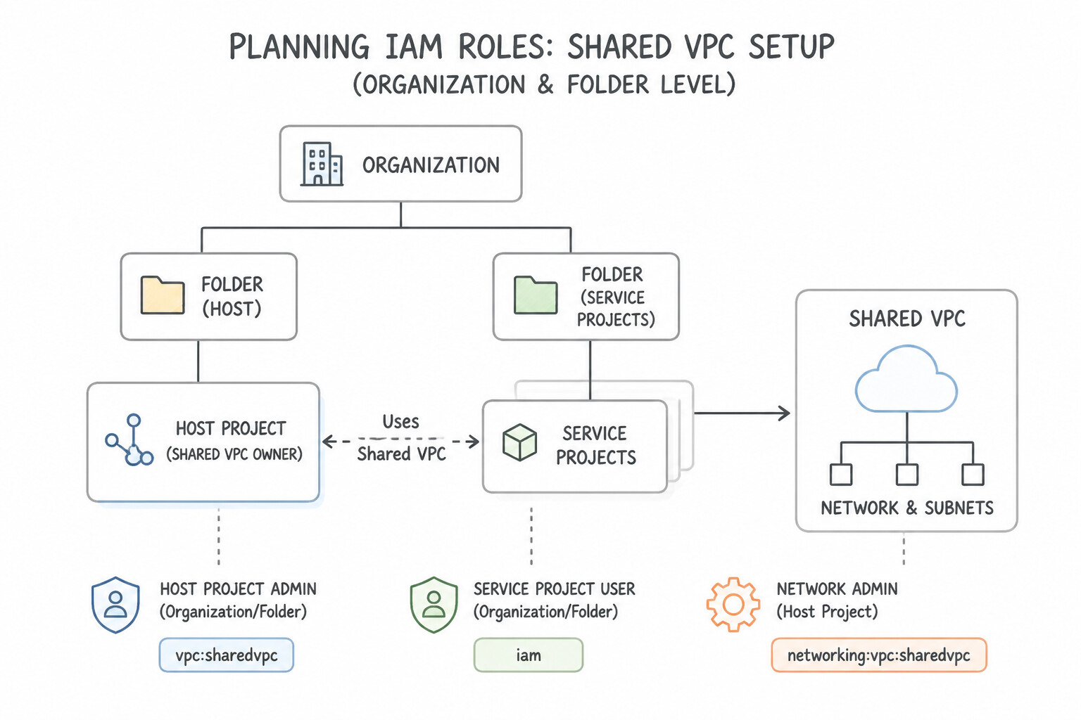
In Google Cloud architectures, you must always select the least-privilege IAM role assigned at the narrowest resource scope:
- Shared VPC Setup (
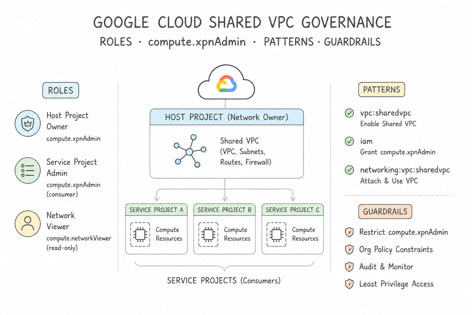
Organization/FolderLevel): roles/compute.xpnAdmin(Compute Shared VPC Admin): Required to enable a project as a Shared VPC Host Project and attach Service Projects to it.- Shared VPC Subnet Consumption (
Host ProjectSubnet Level): roles/compute.networkUser(Compute Network User): Grant this role to Service Project user principals, the Compute Engine default service account, and the Google APIs Service Agent (PROJECT_NUMBER@cloudservices.gserviceaccount.com) on the specific individual subnets in the Host Project—never at the entire Host Project level if teams must be isolated to their own subnets!- For GKE in a Shared VPC, also grant
roles/container.hostServiceAgentUser(Kubernetes Engine Host Service Agent User) to the Service Project's GKE service account (service-SERVICE_PROJECT_NUMBER@container-engine-robot.iam.gserviceaccount.com) on the Host Project. - Separation of Duties inside the Network Team:
roles/compute.networkAdmin(Compute Network Admin): Full control over VPCs, subnets, routes, load balancers, Cloud Routers, and VPNs—except it cannot modify firewall rules or SSL certificates!roles/compute.securityAdmin(Compute Security Admin): Manages firewall rules, Cloud NGFW policies, Cloud Armor security policies, and SSL certificates.roles/compute.loadBalancerAdmin(Compute Load Balancer Admin): Least-privilege role for application teams that only need to provision load balancers, URL maps, backend services, and health checks without modifying VPC subnets or routes.
Key Implementation Patterns
- Granular Subnet Access Control: Use Grant the Compute Network User role to the Finance team on the 'finance-subnet' resource in the host project. Granting the role on the specific subnet resource ensures the team can only access that network and no others. (Avoid alternative: This grants access to all subnets in the project, violating the least privilege requirement.)
- Enabling Shared VPC Host: Use Grant the network engineering team the Compute Shared VPC Admin role at the Organization level. The Compute Shared VPC Admin role at the Organization level allows enabling host projects and managing attachments. (Avoid alternative: Compute Network Admin manages network resources inside a project, not the Shared VPC configuration itself.)
- GKE Cluster Deployment in Shared VPC: Use In the host project, grant the Kubernetes Engine Host Service Agent User role to the GKE Service Agent of the service project. The Kubernetes Engine Host Service Agent User role grants the necessary permissions for the GKE robot account to manage network resources in the host project.
Key Takeaways (1.1f)
- Shared VPC separates network administration (Host Project) from resource creation (Service Project).
- The
compute.networkUserrole is required to attach resources to a subnet.- Permissions should be granted at the subnet level in the Host Project to ensure granular access control and adhere to the principle of least privilege.
- Shared VPC allows multiple service projects to use a common network in a host project.
Consideration 1.1g: Planning connectivity to managed services (Private Service Connect, PSA, Serverless VPC Access)
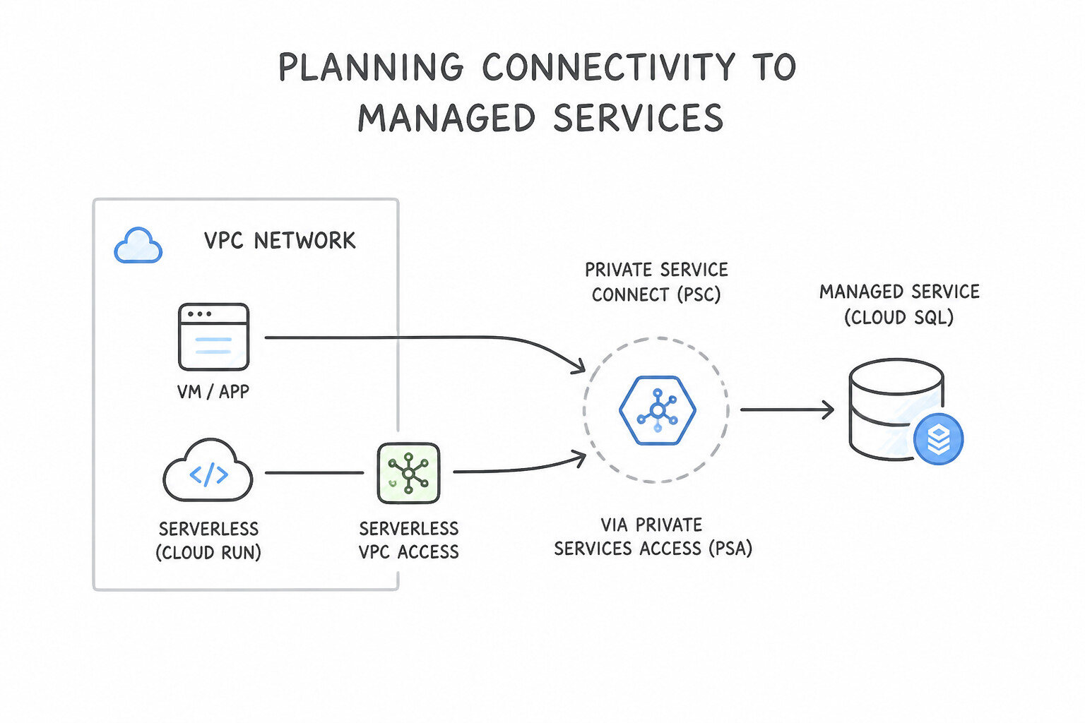
Distinguishing Google Cloud's three managed-service connectivity models is essential:
- Private Services Access (
PSA): - How it works: Allocates an internal
/16–/24IP range in your VPC and establishes VPC Network Peering with a Google-managed producer VPC (used by Cloud SQL, Memorystore, Filestore, Vertex AI Training/Pipelines). - Limitation: Because PSA uses VPC Peering, on-premises hosts or peered consumer VPCs cannot transitively reach the PSA producer subnet unless you export custom routes on the PSA peering connection (
gcloud services vpc-peerings update --export-custom-routes) or use a proxy/PSC. - Private Service Connect (
PSC): - How it works: Projects a producer service (Google APIs, Cloud SQL PSC instance, Memorystore Cluster, Apigee, or a third-party SaaS Internal LB) directly into the consumer VPC as a local PSC Endpoint (
ForwardingRule) or PSC Backend (NEG) using NAT. - Superpower: Zero VPC Peering required, tolerant of overlapping IP addresses, works transitively across hybrid VPN/Interconnect (by advertising the consumer PSC endpoint IP), and enforces unidirectional consumer-to-producer initiation.
- Serverless Connectivity (
Direct VPC Egressvs.Serverless VPC Access Connector): - Allows Cloud Run, Cloud Functions, and App Engine Standard to send traffic to internal VPC IPs.
- Prefer Direct VPC Egress for Cloud Run (assigns IPs directly from a regular subnet with lower latency and zero connector VM cost); use a Serverless VPC Access Connector (requires a dedicated
/28subnet in the region) when required by App Engine, Cloud Functions Gen 1, or network tags on connector instances.
Key Implementation Patterns
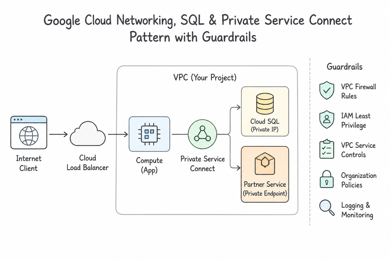
- Cloud SQL Private Access Configuration: Use Allocate a reserved IP address range in your VPC and create a private service connection to the service producer network. Cloud SQL requires Private Services Access, which involves allocating an IP range and creating a private peering connection.
- Secure Consumption of Google APIs: Use Configure a Private Service Connect endpoint using a global internal IP address that targets the all-apis bundle. Private Service Connect creates a specific internal IP endpoint in your VPC to access Google APIs, satisfying the security requirement.
Key Takeaways (1.1g)
- Cloud SQL instances on private IP addresses reside in a Google-managed VPC (service producer network).
- Private Services Access (PSA) is the mechanism to connect your VPC to the service producer network.
- PSA requires allocating a dedicated internal IP range and creating a private connection (VPC Peering).
- Private Service Connect (PSC) allows access to Google APIs via a user-defined internal IP address within the VPC.
Consideration 1.1h: Differentiating between network tiers (Premium and Standard)
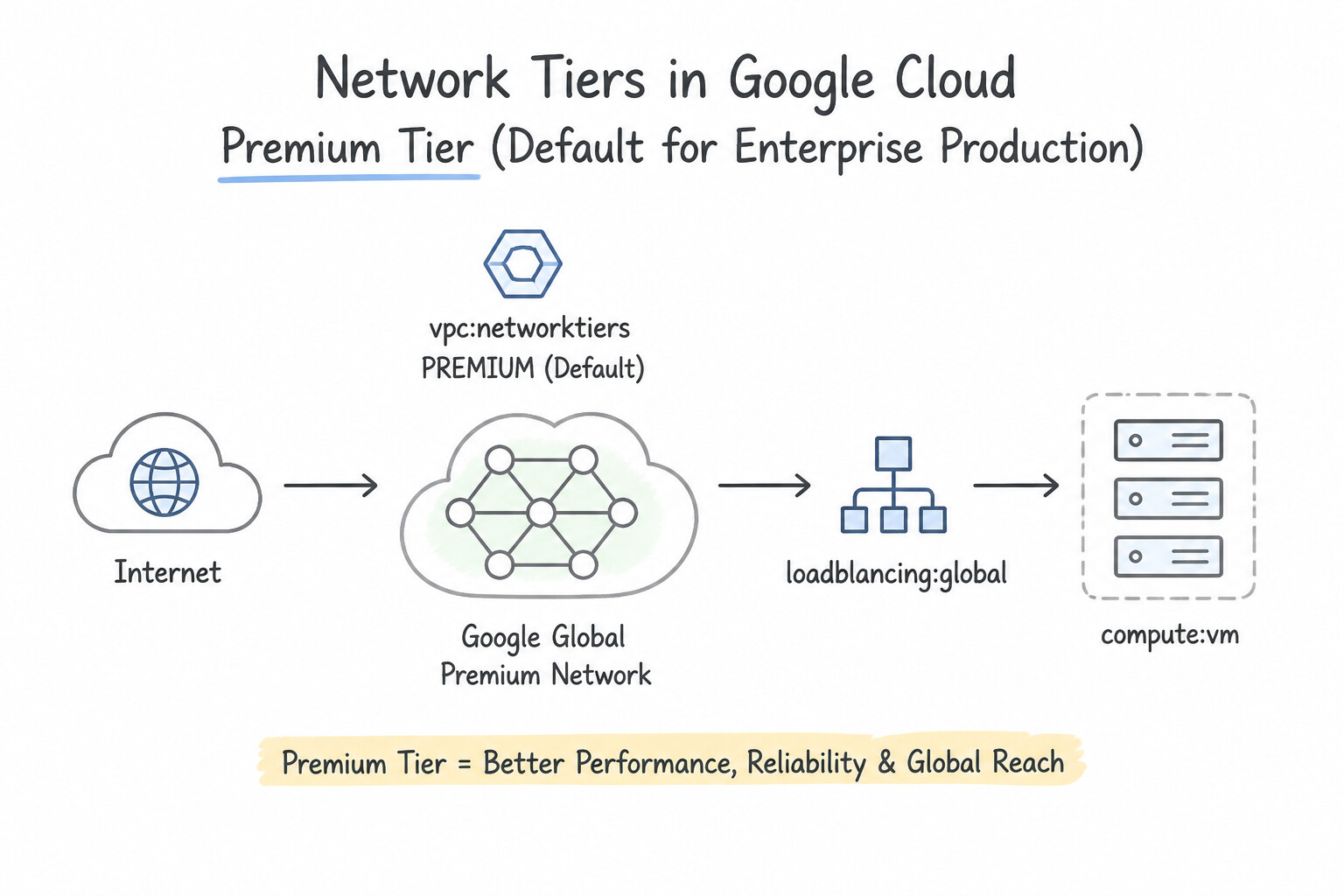
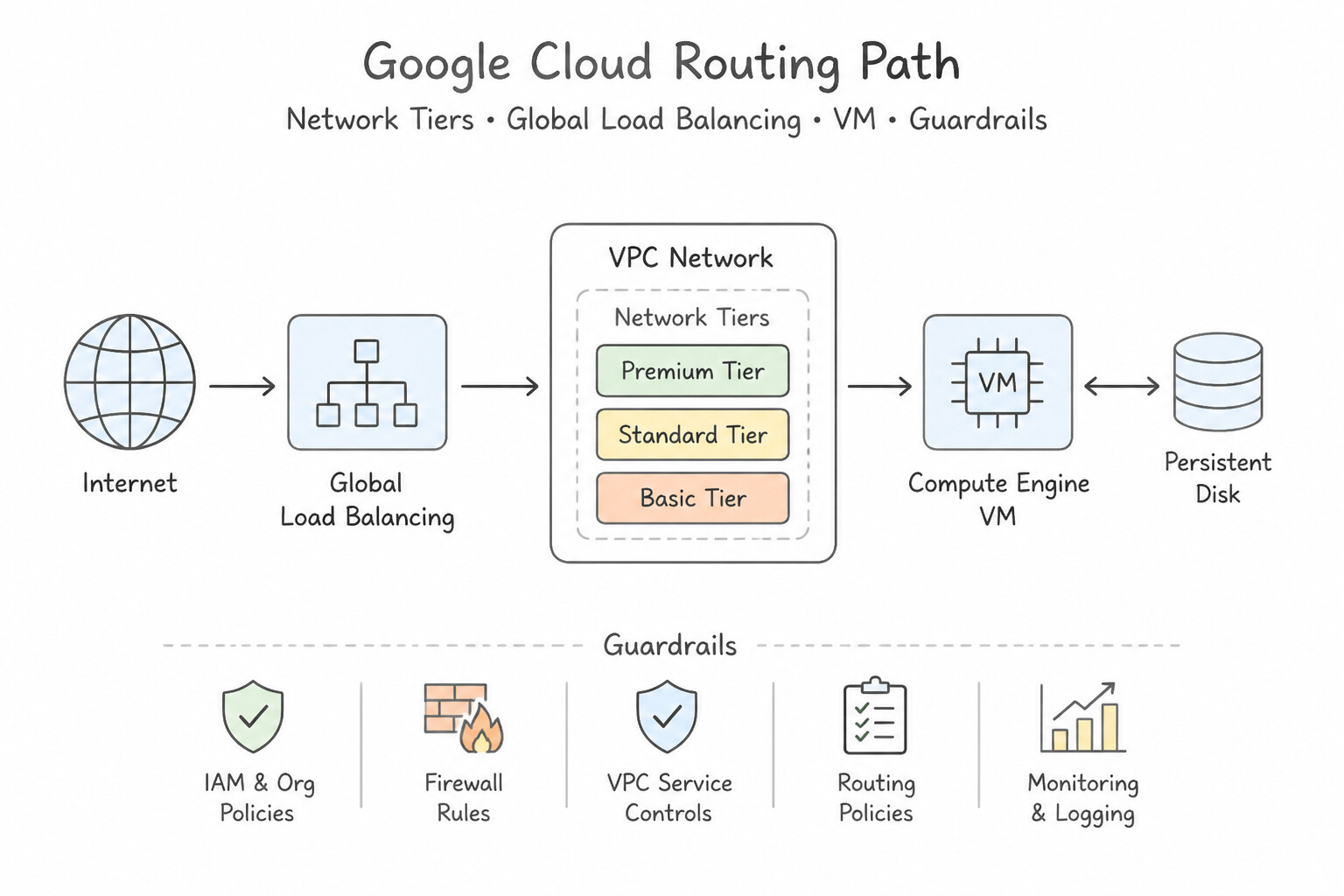
- Premium Tier (Default for Enterprise Production):
- Routing Path: Cold-potato routing—user traffic enters Google's private fiber network at the PoP closest to the user (over 200+ edge locations) and rides Google's redundant global backbone all the way to the backend region.
- Exclusive Capabilities: Required for Global External Load Balancers (Anycast VIP serving backends in multiple regions) and Cloud CDN with global multi-region backends.
- Standard Tier (Cost-Optimized Single-Region Workloads):
- Routing Path: Hot-potato routing—egress traffic exits Google's network immediately at the region where the VM resides and traverses the public ISP internet; ingress traffic travels over public ISPs until reaching the specific GCP region.
- Limitations: External IP addresses and load balancers in Standard Tier are strictly Regional. You cannot use a Global Anycast IP or multi-region backend service in Standard Tier.
- Planning for Quotas and Limits:
- Understand the difference between Soft Quotas (can be increased via Cloud Quotas console/API, such as regional CPUs, static external IPs, forwarding rules) and Hard Architectural Limits (cannot be increased, such as
25max peerings per VPC,30max secondary IP ranges per subnet,8max vNICs per VM, or/29minimum subnet size).
Key Implementation Patterns
- Global Load Balancing Requirements: Use Select the Premium Tier for the external IP address configuration. Premium Tier supports global Anycast IP addresses required for multi-region global load balancing. (Avoid alternative: This option uses multiple IP addresses instead of the required single Anycast IP.)
- Cost Optimization for Regional Workloads: Use Configure the external IP addresses of the VMs to use the Standard Tier. Standard Tier is cost-effective for single-region workloads with local users. (Avoid alternative: Premium Tier is more expensive and designed for high-performance global routing.)
- Cloud CDN Integration: Use Configure the load balancer frontend to use the Premium Network Tier. Cloud CDN requires the Premium Network Tier because it relies on Google's global network and global load balancers. (Avoid alternative: The Standard Network Tier does not support the global load balancing features required for Cloud CDN.)
Key Takeaways (1.1h)
- Premium Tier is required for Global Load Balancing and single Anycast IP addresses.
- Standard Tier is lower cost but uses regional IPs and the public internet for transit.
- Anycast IPs simplify DNS and client configuration by using one address worldwide.
- Premium Tier is the default and optimizes for performance by keeping traffic on Google's global backbone.
Quick Decision Cheat Sheet (Subsection 1.1)
If the Scenario Requires... | Choose This Google Cloud Pattern | Avoid This Common Mistake |
|---|---|---|
"Minimize latency for global users + single global Anycast IP + multi-region failover" | Premium Network Tier + Global External Application Load Balancer | Standard Network Tier; Regional Load Balancer with manual DNS updates |
"Single-region workload + minimize outbound egress bandwidth cost + latency over public ISP is acceptable" | Standard Network Tier with a Regional Load Balancer | Premium Network Tier; Global Load Balancer |
"Enable Shared VPC on a Host Project and attach Service Projects" | roles/compute.xpnAdmin (Compute Shared VPC Admin) at Org/Folder level | roles/compute.networkAdmin or roles/owner on the service project |
"Allow Service Project GKE cluster or MIG to deploy into a specific Shared VPC subnet" | roles/compute.networkUser on the specific subnet + roles/container.hostServiceAgentUser (for GKE) | Project-wide compute.networkAdmin on the Host Project |
"GKE cluster creation or node pool scaling fails with IP_SPACE_EXHAUSTED on a /21 Pod range" | Lower --max-pods-per-node (so each node claims a /26 or /27 instead of /24) or add a new secondary range | Trying to shrink an existing node pool's /24 allocation in place without recreating the node pool |
"Private VMs without external IPs must reach Google APIs while enforcing VPC Service Controls" | Enable Private Google Access + CNAME *.googleapis.com to restricted.googleapis.com (199.36.153.4/30) | Using private.googleapis.com (199.36.153.8/30) or deploying Cloud NAT for Google APIs |
"Cloud Run / Cloud Functions must connect to a private Cloud SQL IP ( Private Services Access)" | Configure Direct VPC Egress or a Serverless VPC Access Connector (dedicated /28 subnet) | Enabling only Private Google Access (PGA only reaches Google public API VIPs, not RFC 1918 PSA subnets) |
Further Reading (Subsection 1.1)
- Establishing 99.99% availability for Dedicated Interconnect — This section of the documentation details the specific topology requirements (two metros, two zones per metro) needed to achieve the 99.99% SLA.
- Cloud VPN Overview — Provides a high-level comparison of HA VPN versus Classic VPN and explains the requirements for 99.99% availability.
- HA VPN topologies — Details the topology requirements, including the necessity of configuring two tunnels and using BGP.
- Manage zones and records — Provides the foundational definitions of Public and Private zones in Cloud DNS.
- DNS zones overview — Specifically discusses the split-horizon configuration where a private zone and a public zone share the same DNS name.
- Cloud DNS Forwarding Zones — Documentation explaining how forwarding zones work to route queries to alternative name servers.
Subsection 1.2: Designing VPC networks
The Big Picture
A Google Cloud VPC is a global virtual network whose subnets are regional—a foundational design advantage over legacy cloud providers where every region requires a separate VPC and complex cross-region peering. Yet enterprise architects routinely sabotage this simplicity in three ways:
- The Auto-Mode & Overlapping CIDR Trap: Spinning up
auto-modeVPCs creates predetermined10.128.0.0/9subnets in every region. The moment two projects try to peer or connect to on-premises networks, identical CIDRs collide. Even worse, teams that run out ofRFC 1918space after an M&A acquisition attempt to peer overlapping VPCs directly instead of deploying Private NAT with Network Connectivity Center (NCC) or Private Service Connect (PSC). - The Peering Sprawl & Limit Trap: Native VPC Network Peering is strictly non-transitive and caps at 25 peerings per VPC (and has total dynamic/subnet route group limits across a peering group). Teams that build a 30-VPC full mesh via native peering hit hard control-plane ceilings, whereas Network Connectivity Center (
NCC) VPC Spokes scale to hundreds of VPCs in a centralized hub-and-spoke (StarorMesh) topology. - The MTU Mismatch & NVA Hairpin Trap: Enabling Jumbo Frames (
8896bytes) inside a VPC for high-performance computing (HPC) without matching the MTU across communicating VMs—or sending jumbo frames over an HA VPN (1460max) or Cloud Interconnect (1440–8896) without path MTU discovery—causes silent packet blackholes for large payloads while smallpingpackets succeed.
Consideration 1.2a: Choosing VPC type and quantity (standalone or Shared VPC)
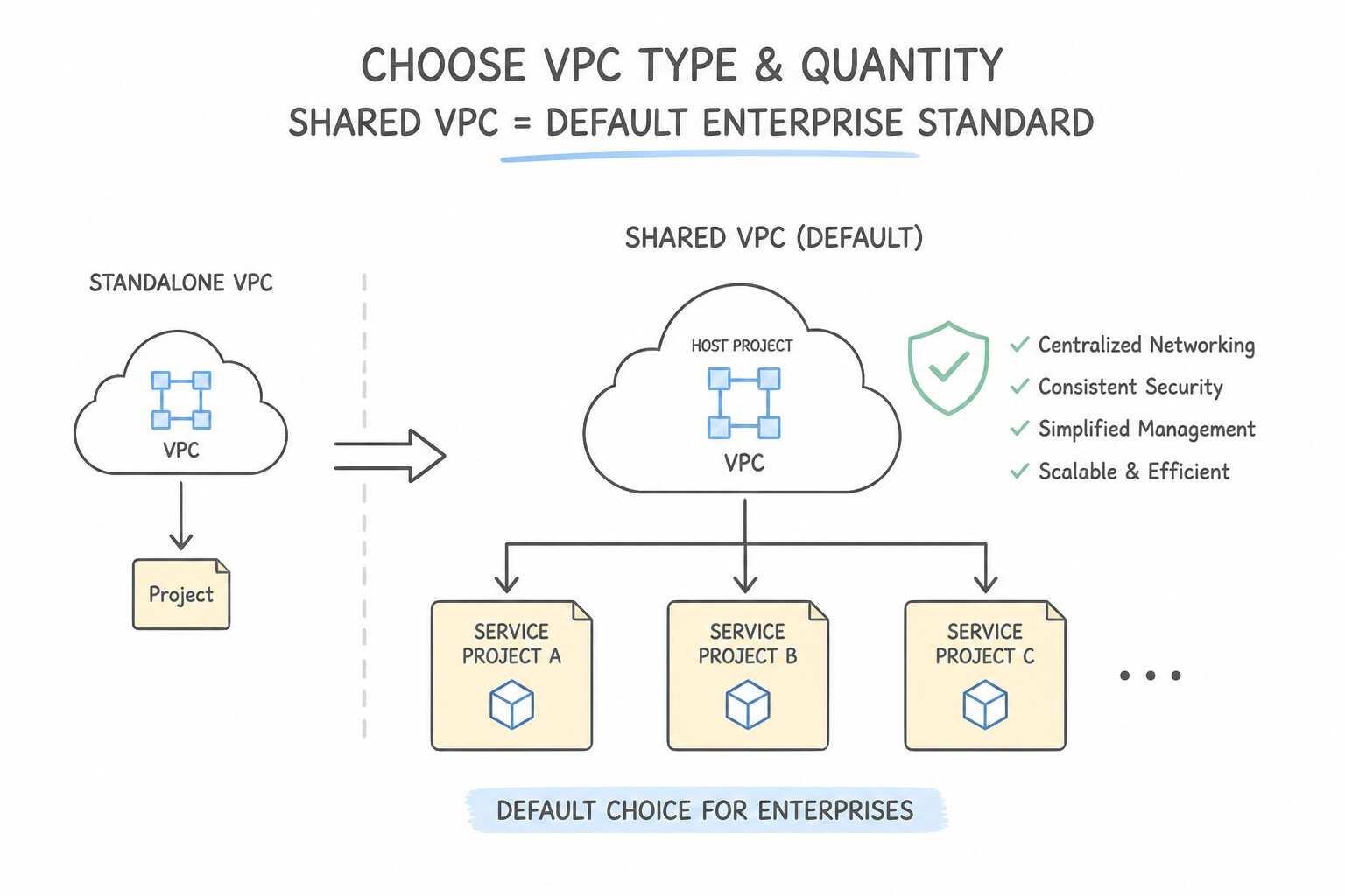
- Shared VPC is the Default Enterprise Standard: When multiple application teams within the same environment tier (e.g.,
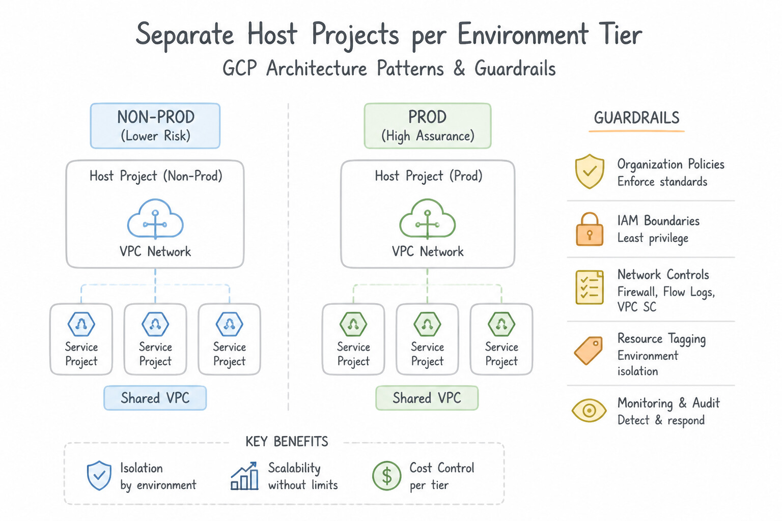
Production) need centralized network governance, firewall enforcement, and hybrid connectivity while keeping their own project billing and IAM autonomy, use Shared VPC (1 Host Project + many Service Projects). - Separate Host Projects per Environment Tier (
Prodvs.Non-Prod): Google Cloud best practice is to create separate Shared VPC Host Projects forProduction,Staging, andDevelopmentto enforce hard blast-radius and routing isolation between environments. - Key Architectural Constraints of Shared VPC:
- A Service Project can be attached to at most ONE Shared VPC Host Project at a time (though a Service Project can still contain its own standalone VPCs).
- A project cannot be both a Host Project and a Service Project simultaneously.
- Both the Host Project and all attached Service Projects must belong to the same Google Cloud Organization.
- When to Choose Standalone VPCs: Use standalone VPCs for completely independent subsidiaries, external partners, sandbox projects outside the main Org, or multi-NIC inspection hubs.
Key Implementation Patterns
- Separation of Duties (Network vs. Application): Use Configure a Shared VPC with a host project for the network team and service projects for application teams. Shared VPC separates network administration (Host Project) from instance creation (Service Projects), matching the scenario.
- Strict Regulatory Isolation: Use Create a new project and configure a standalone VPC network for the application. A standalone VPC in a separate project creates a distinct boundary for IAM and network control, satisfying strict compliance needs. (Avoid alternative: Shared VPC involves a shared network control plane in the host project, violating the strict isolation requirement.)
- Environment Isolation (Prod vs. Non-Prod): Use Create two separate Shared VPCs: one for Production and one for Development. Attach service projects to the corresponding host project. Separate Shared VPCs provide complete routing isolation and blast radius reduction while allowing centralized management.
Key Takeaways (1.2a)
- Shared VPC allows a Host Project to share a network with Service Projects.
- Shared VPC is the primary solution for separating network administration from service administration.
- VPC Peering connects independent networks but does not centralize administration of those networks.
- Always follow the principle of least privilege when assigning roles.
Consideration 1.2b: Determining interconnect approach (VPC Peering, NCC mesh/star, Private Service Connect)
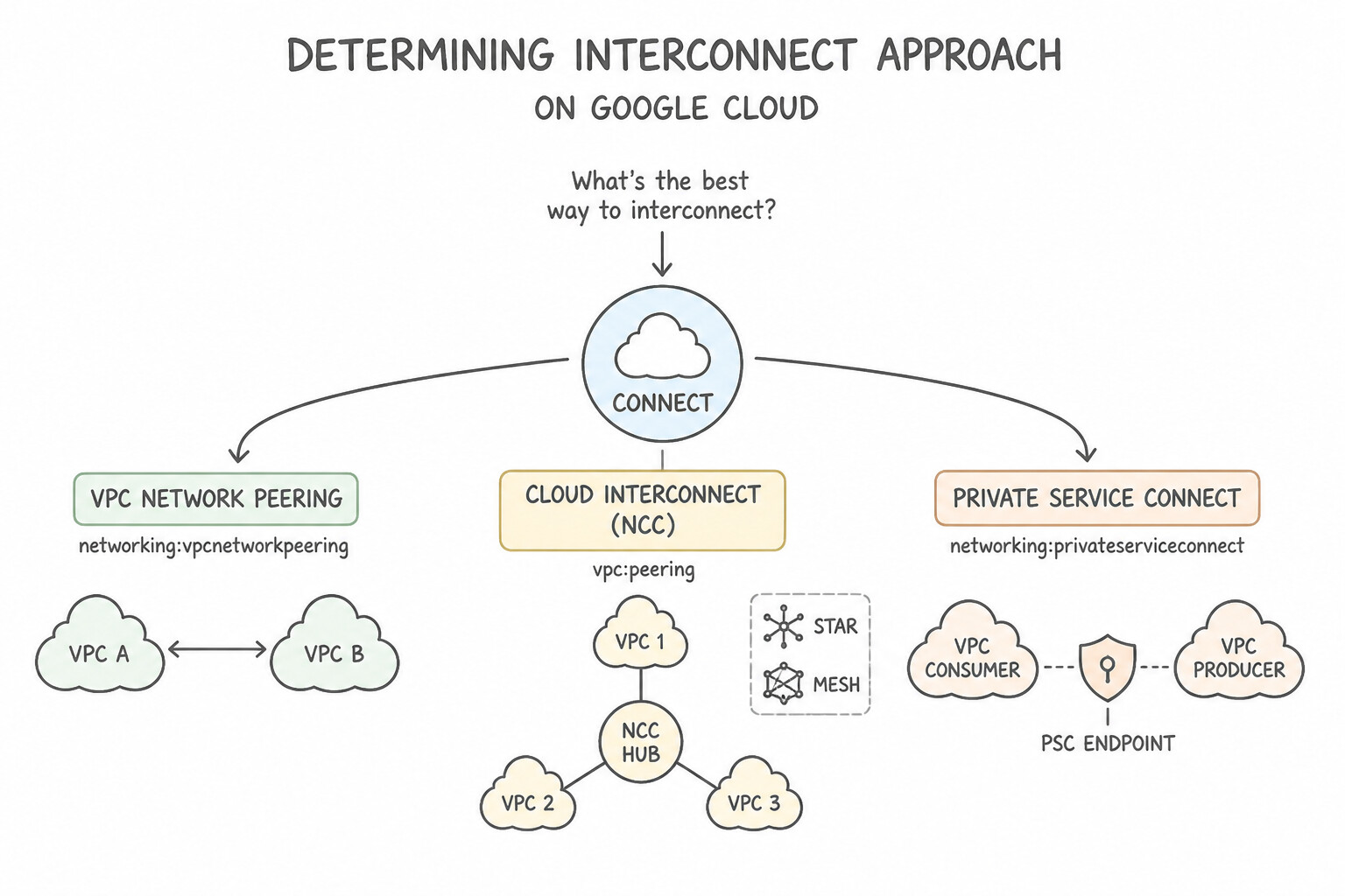
- VPC Network Peering:
- Data-plane direct L3 routing with zero bandwidth charges beyond normal zone egress.
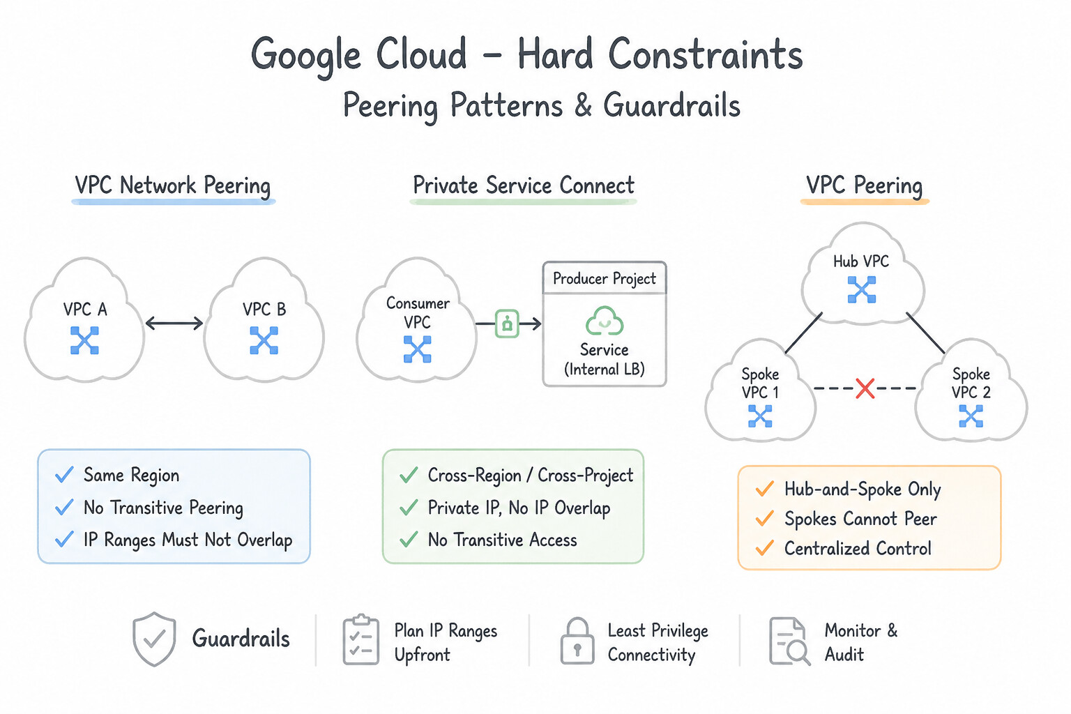
- Hard Constraints: Strictly non-transitive, no overlapping CIDRs allowed, max 25 peerings per VPC, and does not support
Secure Tagsacross legacy VPC firewall rules (only IP ranges, though Cloud NGFW policies support cross-VPC Secure Tags). - Network Connectivity Center (
NCC): - Mesh Topology: All VPC spokes in the
defaultgroup exchange subnet routes with every other spoke (up to 250+ VPC spokes without hitting the 25-peer limit!). - Star Topology: Divides VPC spokes into two groups: Center (Core) Spokes (e.g., Shared Services / Inspection VPCs) and Edge Spokes (workload VPCs). Edge spokes can communicate with Center spokes, but Edge spokes cannot communicate directly with other Edge spokes unless routed through a Center NVA.
- Private Service Connect (
PSC): - Best when connecting service producers to service consumers across different trust domains, organizations, or overlapping IP ranges, where full L3 network peering is either impossible or overly permissive.
Key Implementation Patterns
- Handling Overlapping IP Ranges in Acquisitions: Use Configure the API in Company B as a published service using Private Service Connect and create an endpoint in Company A. Private Service Connect allows access to specific services across VPCs even if their IP ranges overlap.
- Enabling Transitive Routing for Hub-and-Spoke: Use Replace the VPC Network Peering connections with Cloud VPN tunnels. VPC Peering is non-transitive. Cloud VPN supports transitive routing, allowing traffic to pass through the Hub VPC. (Avoid alternative: Direct peering creates a path that bypasses the Hub VPC, violating the requirement to route traffic through the Hub.)
- High-Performance Data Transfer Between Internal VPCs: Use Set up VPC Network Peering between 'VPC-App' and 'VPC-Data'. VPC Network Peering offers the lowest latency and highest throughput for connecting VPCs in the same organization. (Avoid alternative: Cloud VPN introduces encryption overhead and bandwidth limits, making it slower than peering for same-region VPC connections.)
Key Takeaways (1.2b)
- VPC Network Peering requires non-overlapping IP address ranges.
- Private Service Connect (PSC) is the preferred method to publish and consume services across VPCs that have overlapping IP ranges.
- PSC connects to specific services, whereas Peering connects entire networks.
- Avoid re-addressing networks (IP changes) by using service-oriented connectivity like PSC.
Consideration 1.2c: Planning IP strategy including IPv6, BYOIP, Private NAT, managed services
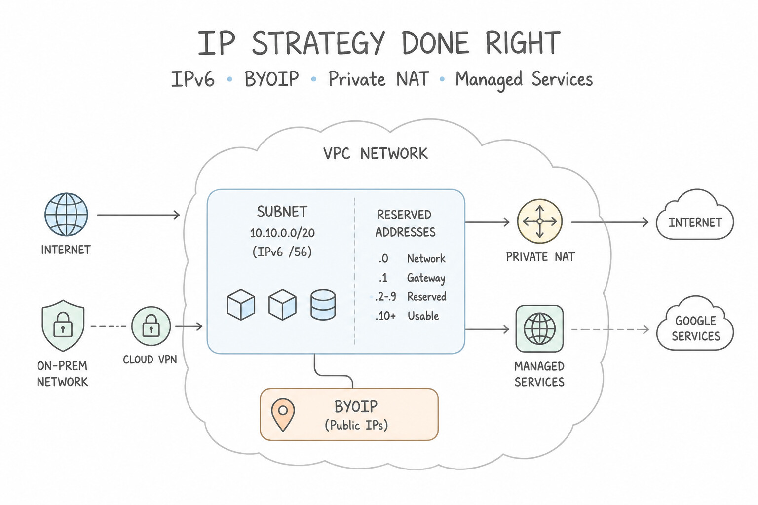
- Subnet Sizing & Reserved Addresses:
- Every Google Cloud IPv4 subnet reserves 4 IP addresses (
first= network address,second= default gateway.1,second-to-last= reserved for future use,last= broadcast). - Minimum subnet mask is
/29($8 - 4 = \mathbf{4\text{ usable IPs}}$); maximum is/8. - Subnets can be expanded dynamically (e.g.,
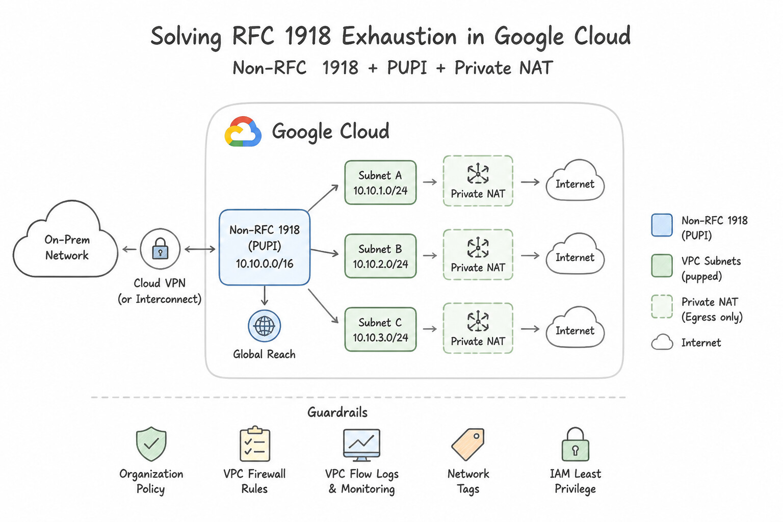
/24→/20) with zero downtime, but can never be shrunk! - Solving RFC 1918 Exhaustion (
Non-RFC 1918,PUPI,Private NAT): - Non-RFC 1918 (
100.64.0.0/10Carrier-Grade NAT / RFC 6598,240.0.0.0/4Class E): Supported inside VPCs and high-density GKE Pod ranges without consuming precious on-premises RFC 1918 space. - Privately Used Public IPs (
PUPI): Using any public IPv4 block internally inside a VPC/GKE Pod range without advertising it to the internet. Note: to advertise PUPI routes over BGP across Cloud Router orVPC Peering, you must explicitly enable--enable-privately-used-public-ips. - Private NAT: Performs source NAT (
SNAT) between overlapping VPC spokes in an NCC Hub or between an on-premises hybrid spoke and a VPC, translating overlapping source IPs into a dedicated non-overlappingPrivate NATsubnet (--purpose=PRIVATE_NAT). - Bring Your Own IP (
BYOIP): Lets you import your own publicly routable/24+ IPv4 block via a Public Advertised Prefix (PAP) (verified via BGP ROA and DNS PTR) and subdivide it into regional/global Public Delegated Prefixes (PDPs) for external VMs, Load Balancers, or Cloud NAT. - IPAM Automation (
InternalRangeAPI): Use Network Connectivity Center's Internal Ranges API (gcloud network-connectivity internal-ranges create) to reserve CIDR blocks across VPCs and prevent accidental IP collisions in CI/CD Terraform pipelines.
Key Implementation Patterns
- Private NAT for Hybrid Connectivity: Use Create a Private NAT gateway rule on a Cloud Router to translate the overlapping subnet IP addresses. Private NAT allows communication between networks with overlapping IP addresses by translating them automatically. (Avoid alternative: Cloud NAT is used for internet access, not for internal private connectivity between overlapping networks.)
- Dual-Stack Subnets for External IPv6: Use Edit the subnet to use the External IPv6 access type. External IPv6 access configures the subnet to assign public IPv6 addresses that are routable from the internet. (Avoid alternative: Internal IPv6 access allows communication only within the VPC or connected private networks, not the internet.)
Key Takeaways (1.2c)
- Overlapping IP ranges prevent direct routing between networks.
- Private NAT is the specific Google Cloud solution for handling overlapping IPs in hybrid or inter-VPC connectivity.
- Cloud NAT is primarily for internet access, not private network interconnection.
- Avoiding IP overlap during the planning phase is best, but Private NAT resolves legacy conflicts.
Consideration 1.2d: Planning global versus regional environments
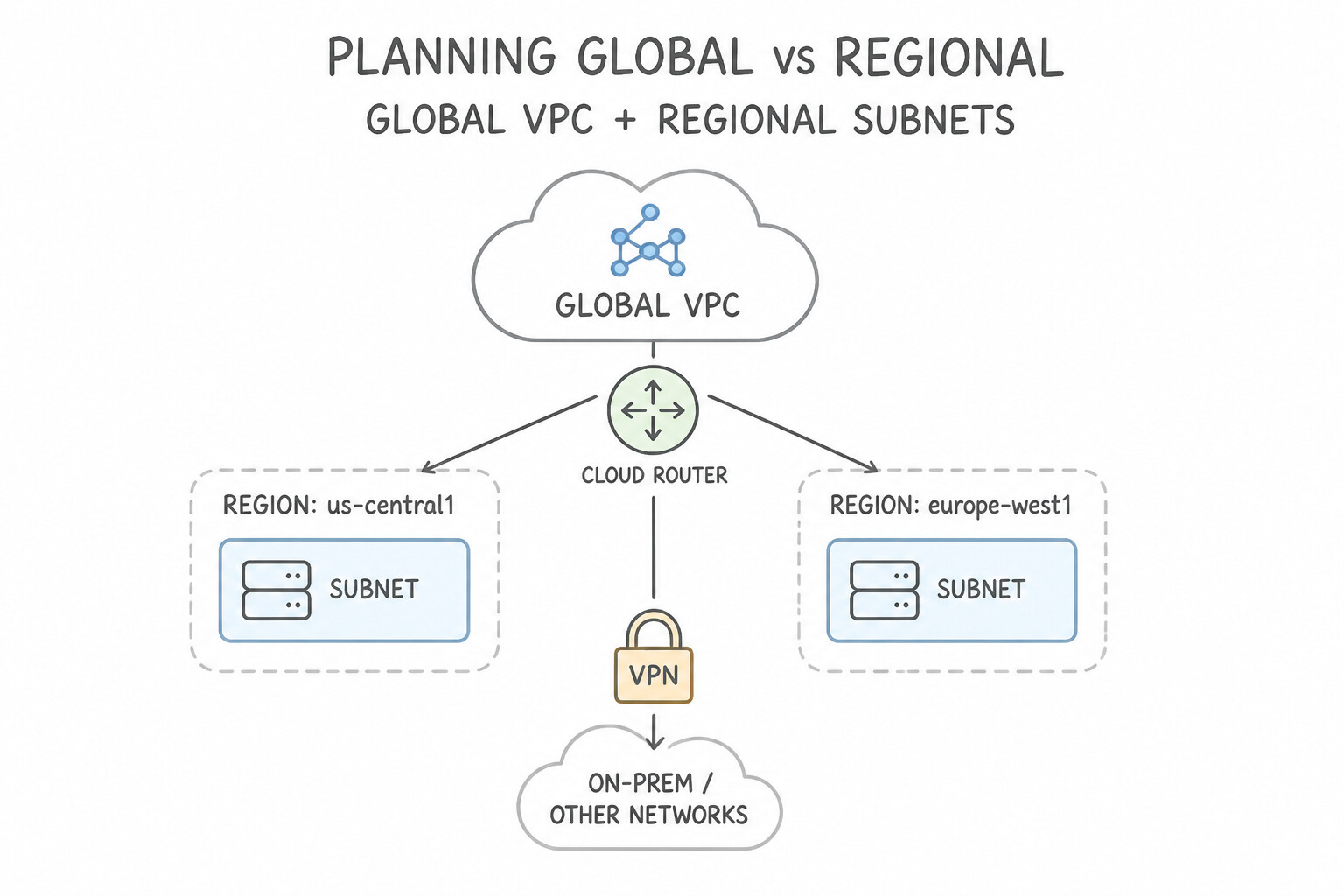
- Global VPC + Regional Subnets: A single VPC spans all Google Cloud regions worldwide without needing VPNs or peering between regions. Subnets live inside a single region and automatically span all Availability Zones in that region.
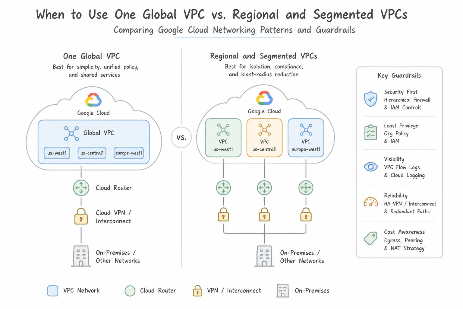
- When to Use One Global VPC vs. Regional/Segmented VPCs:
- Use a single global VPC (or Shared VPC) per environment tier when workloads across regions collaborate and share global load balancers, Cloud Routers, and centralized DNS.
- Split into separate VPCs when strict regulatory blast-radius isolation, separate administrative ownership, or multi-NIC inspection firewalls between security zones (
Untrusted DMZ VPC→NVA→Trusted Internal VPC) are required.
Key Implementation Patterns
- Dynamic Routing Mode for Multi-Region Hybrid Connectivity: Use Change the dynamic routing mode of the VPC network to Global. Global dynamic routing enables Cloud Routers to advertise subnets from all regions, not just their local region. (Avoid alternative: Adding more gateways is unnecessary and costly; the existing gateway can advertise all routes if configured correctly.)
- Data Sovereignty within a Global VPC: Use Create a VPC network in custom mode. Define a single subnet within the 'europe-west3' region. VPCs are global, but subnets are regional. Custom mode allows you to create subnets only in the specific regions required for compliance.
- Cloud NAT Planning for Multi-Region Outbound Traffic: Use Create a separate Cloud Router and Cloud NAT gateway in the Europe and Asia regions. Cloud NAT is a regional resource; you must deploy a gateway in each region where outbound internet access is required. (Avoid alternative: Global dynamic routing allows cross-region learning for hybrid connections, but it does not expand Cloud NAT's regional scope.)
Key Takeaways (1.2d)
- VPC networks are global resources, but Cloud Routers are regional resources.
- VPC Dynamic Routing mode determines the scope of routes a Cloud Router can manage.
- Regional mode (default) limits advertisements to the local region.
- Global mode extends advertisements to all subnets in the VPC across all regions.
Consideration 1.2e: Determining MTU sizing
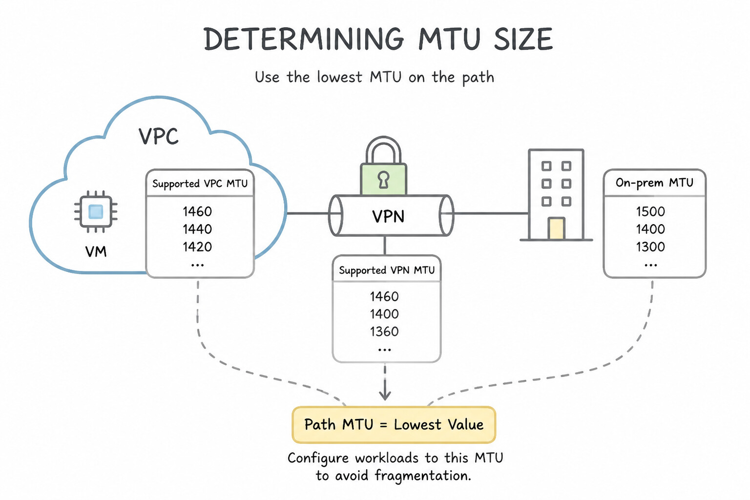
- Supported VPC MTU Values:
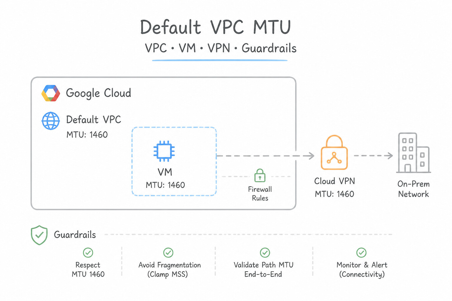
- Default VPC MTU:
1460bytes (historically optimized for encapsulation overhead). - Standard Ethernet MTU:
1500bytes. - Maximum Jumbo Frame MTU:
8896bytes (configured at the VPC level; supports up to8896-byte frames between VMs in the same VPC or across peered VPCs that both configure8896MTU, using Google's gVNIC driver). - Critical MTU Rules in Production:
- Both communicating VPCs/VMs must match MTU: If
VPC-Auses8896MTU andVPC-Buses1460MTU over VPC Peering, unfragmented jumbo packets (DF=1) fromVPC-AtoVPC-Bwill be dropped! - Hybrid Tunnel MTU Ceilings: HA VPN supports a maximum payload MTU of
1460bytes (or1440bytes for encrypted Interconnect VLAN attachments); Cloud Interconnect supports1440,1460,1500, or8896bytes (jumbo frames). Never send8896-byte packets into an IPsec VPN tunnel!
Key Implementation Patterns
- HPC Throughput Optimization: Use Configure the VPC network MTU to 8896 bytes. MTU 8896 (Jumbo Frames) maximizes throughput and reduces CPU usage by sending larger payloads per packet. (Avoid alternative: 1460 bytes is the default MTU size and does not provide the throughput optimization or CPU overhead reduction of jumbo frames.)
- Cloud VPN MTU Constraints: Use Configure TCP MSS clamping on the on-premises VPN gateway. MSS clamping limits the data segment size so the final packet fits through the tunnel with overhead included. (Avoid alternative: Changing the VPC MTU to 1500 bytes ignores the additional packet overhead required by the VPN tunnel.)
- Dedicated Interconnect Jumbo Frames: Use Set the VPC network MTU to 8896. Update the Interconnect attachment to use an MTU of 8896. Jumbo Frames in Google Cloud require an MTU of 8896 on both the VPC network and the Interconnect VLAN attachment. (Avoid alternative: An MTU of 1500 is for standard Ethernet, not Jumbo Frames (which require 8896 bytes).)
Key Takeaways (1.2e)
- MTU 8896 (Jumbo Frames) is used to maximize throughput and reduce CPU overhead for internal VPC traffic.
- The default MTU in Google Cloud is 1460 bytes.
- Ensure both the VPC network and the OS on the VMs are configured with the matching MTU size.
- The default MTU for Google Cloud VPC is 1460 bytes.
Consideration 1.2f: Planning third-party device insertion and custom routing
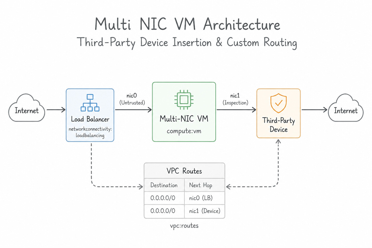
- Multi-NIC VM Architecture: A Network Virtual Appliance (such as Palo Alto VM-Series, Fortinet FortiGate, Check Point) runs on a Compute Engine VM with 2 to 8 vNICs (
nic0..nic7), where every vNIC must attach to a different VPC network (e.g.,nic0inUntrusted-VPC,nic1inTrusted-VPC,nic2inMgmt-VPC) and--can-ip-forwardenabled. - High Availability via Internal Passthrough Load Balancer (
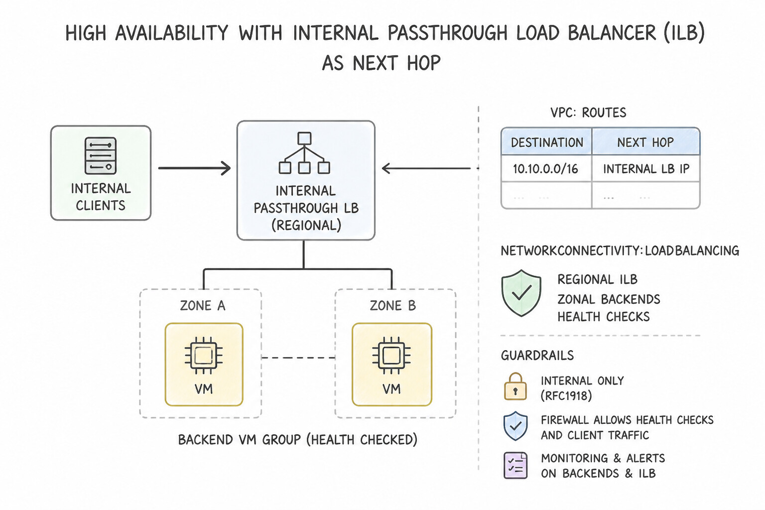
ILB) as Next Hop: - Never point a static route at a single NVA VM instance (creates a single point of failure).
- Place an autoscaled/redundant Managed Instance Group of NVAs behind an Internal Passthrough Network Load Balancer in each VPC, enable symmetric hashing, and configure custom static routes or Policy-Based Routes (
PBR) using the ILB Forwarding Rule as the Next Hop.
Key Implementation Patterns
- High Availability for Network Virtual Appliances: Use Set the next hop to the internal IP address of an internal TCP/UDP load balancer forwarding rule. An internal load balancer as the next hop ensures traffic is only sent to healthy firewall instances automatically. (Avoid alternative: Pointing to a single VM creates a single point of failure and does not support automatic failover.)
- Selective Traffic Inspection via Tags: Use Add a specific network tag to the PCI-compliant VMs. Create a custom static route for destination 0.0.0.0/0, set the next hop to the DLP appliance instance, and specify the network tag. Network tags allow you to apply a static route selectively to specific instances, ensuring only PCI traffic goes to the appliance.
- Multi-NIC Appliance Implementation: Use Create the VM with two network interfaces. Assign the first interface to a subnet in the Untrusted VPC and the second interface to a subnet in the Trusted VPC during creation. Multi-NIC VMs must be configured during creation; you assign each interface to a subnet in a different VPC.
Key Takeaways (1.2f)
- Third-party firewalls and appliances are deployed as VMs (Network Virtual Appliances or NVAs).
- To achieve high availability for NVAs, place them behind an Internal TCP/UDP Load Balancer.
- Configure custom static routes to use the Load Balancer's forwarding rule IP as the next hop.
- This architecture enables automatic fail over and health checking.
Quick Decision Cheat Sheet (Subsection 1.2)
If the Scenario Requires... | Choose This Google Cloud Pattern | Avoid This Common Mistake |
|---|---|---|
"New enterprise greenfield VPC design across regions" | Custom-mode Shared VPC (separate Host Projects for Prod and Non-Prod) | Auto-mode VPC (creates fixed 10.128.0.0/9 subnets that overlap with on-prem) |
"How many usable IP addresses in a /29 Google Cloud subnet?" | 4 usable IPs ($2^3 - 4\text{ reserved} = 4$) | 6 usable IPs (standard on-prem router math) or 8 IPs |
"Connect >25 VPCs in a hub-and-spoke or mesh without hitting VPC Peering limits" | Network Connectivity Center ( NCC) with VPC Spokes | Chaining native VPC Network Peerings (violates non-transitivity and 25-peer limit) |
"Exhausted RFC 1918 space for huge GKE Pod secondary ranges; Pods do not need direct on-prem routing" | Use 100.64.0.0/10 (Shared Address Space), 240.0.0.0/4 (Class E), or PUPI with IP Masquerade / NAT | Expanding primary subnet over existing on-premises RFC 1918 space |
"Small ping packets succeed between two peered VPCs, but large file transfers or TLS handshakes hang" | MTU mismatch (e.g., 8896 jumbo frames on one VPC and 1460 on the other); align MTU or enable MSS clamping | Firewall rule blocking TCP (would block the initial SYN handshake too) |
"Automatically reserve CIDR blocks across projects to prevent Terraform IP collisions" | Internal Ranges API ( InternalRange resource) | Manual spreadsheets or auto-mode VPCs |
Further Reading (Subsection 1.2)
- Shared VPC overview — Read the 'Overview' section to understand how Shared VPC allows an organization to connect resources from multiple projects to a common VPC network.
- VPC network overview — Provides the foundational definition of VPC networks and how they exist within a project.
- Options for connecting to multiple VPC networks — Review the reasons for creating multiple VPCs, specifically for 'Isolation' and separating production from non-production.
- Private Service Connect overview — Provides an overview of Private Service Connect, highlighting its ability to allow private consumption of services across VPC networks without requiring VPC peering or worrying about IP overlap.
- VPC Network Peering restrictions — Lists the restrictions of VPC Network Peering, specifically stating that CIDR ranges cannot overlap.
- Hub-and-spoke architecture — Discusses how Network Connectivity Center and router appliances can be used to create a Hub-and-spoke architecture that supports transitive connectivity.
Subsection 1.3: Designing a resilient and performant hybrid and multi-cloud network
The Big Picture
Hybrid and multi-cloud networking is where physical colocation constraints, BGP routing dynamics, encryption compliance, and cloud SDN abstractions collide. In production, three failure modes dominate:
- The Wrong Physical Link or SLA Topology (
1.3a,1.3b,1.3c,1.3d): Teams choose Direct Peering when they need private RFC 1918 VPC access (Direct Peering only reaches public Google Workspace/YouTube/public API IPs outside the VPC and carries zero SLA!), or they provision two Dedicated Interconnect circuits in a single colocation facility expecting a99.99%SLA (which only qualifies for99.9%because a metro-wide fiber or facility outage severing both circuits violates99.99%dual-metro diversity). - The Transitive Blackhole & API Reachability Trap (
1.3e,1.3f,1.3g): An enterprise lands a 10 Gbps Dedicated Interconnect in a centralTransit-VPCand peersTransit-VPCwith 10Workload-VPCsvia native VPC Network Peering. Because VPC Network Peering does not transitively forward BGP routes from a hybrid link to peered spokes (unless you configure custom route export/import on the direct peer, and even then only 1 hop—never through a chain or to PSA), on-premises hosts cannot reach Cloud SQL (PSA) or Vertex AI in downstream VPCs! - The Unencrypted Fiber & Hybrid MTU Trap (
1.3j,1.3k): By default, Cloud Interconnect does NOT encrypt traffic. Financial and healthcare workloads that assume dedicated fiber equals encryption fail compliance audits unless they layer MACsec for Cloud Interconnect (Layer 2 hardware line-rate encryption on Dedicated Interconnect) or HA VPN over Cloud Interconnect (Layer 3 IPsec encryption, which reduces effective MTU to1440bytes).
Consideration 1.3a: Designing hybrid connectivity (Interconnect, Partner Interconnect, VPN, SD-WAN)
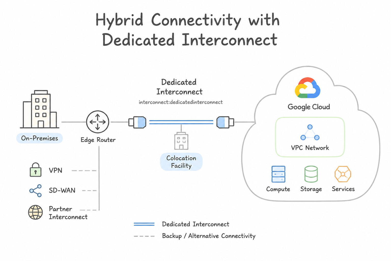
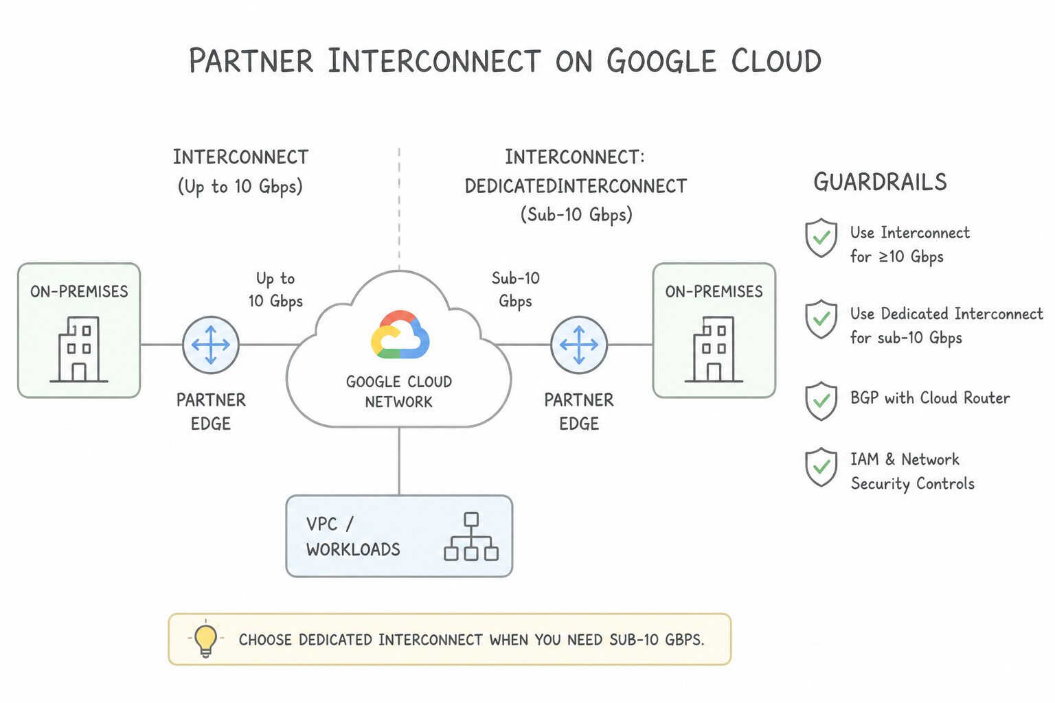
- Dedicated Interconnect: Choose when you need high bandwidth (≥ 10 Gbps) (10 Gbps or 100 Gbps ports, up to $8 \times 10\text{G} = 80\text{ Gbps}or @@ESCAPEDDOLLAR@@2 × 100G = 200 Gbps per link bundle) AND your hardware routers are physically colocated in a Google-supported colocation facility.
- Partner Interconnect: Choose when you need sub-10 Gbps bandwidth (
50 Mbpsto50 Gbps) OR your data center cannot physically reach a Google colocation facility and relies on a carrier/NSP partner. - Cloud HA VPN: Choose when you need rapid deployment (hours instead of weeks), built-in IPsec encryption over the public internet, or bandwidth requirements of 1–3 Gbps per tunnel (scales horizontally via ECMP across multiple tunnels).
- SD-WAN / Branch Office Connectivity: Connect hundreds of retail branches or remote sites using Network Connectivity Center (
NCC) with HA VPN Hybrid Spokes or third-party SD-WAN Router Appliances (RAs) peering via eBGP with Cloud Router.
Key Implementation Patterns
- Achieving 99.99% Availability with Dedicated Interconnect: Use Provision four Dedicated Interconnect connections. Distribute them so that two connections are in one metropolitan area and two connections are in a different metropolitan area. The 99.99% SLA requires four connections spread across two metropolitan areas (two connections per metro).
- Securing Direct Connections with MACsec: Use Enable MACsec for Dedicated Interconnect on the Interconnect attachments. MACsec provides Layer 2 encryption for Dedicated Interconnect without the overhead of IPsec. (Avoid alternative: HA VPN uses IPsec, which operates at Layer 3 and adds overhead, violating the scenario requirements.)
Key Takeaways (1.3a)
- Dedicated Interconnect offers two SLA tiers: 99.9% and 99.99%.
- 99.99% SLA requires 4 connections across 2 different metropolitan areas (2 connections per metro).
- 99.9% SLA requires 2 connections in a single metropolitan area.
- High availability designs must account for both hardware failure (zones) and location failure (metros).
Consideration 1.3b: Designing multi-cloud connectivity (Cloud VPN, Cross-Cloud Interconnect)
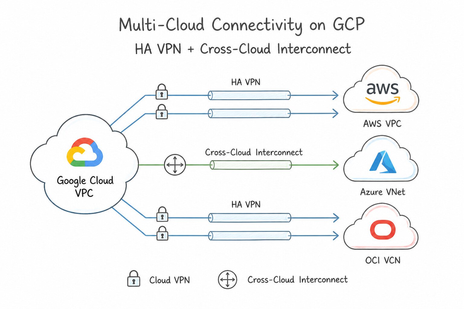
- HA VPN to AWS / Azure / OCI: For low-to-moderate bandwidth (up to several Gbps) with immediate provisioning and native IPsec encryption, pair a Google Cloud HA VPN Gateway (
2 interfaces) with an External Peer VPN Gateway configured withFOUR_IPS_REDUNDANCY(matching AWS Virtual Private Gateway / Transit Gateway's 2 connections × 2 endpoints = 4 tunnels) for a full99.99%SLA. - Cross-Cloud Interconnect (
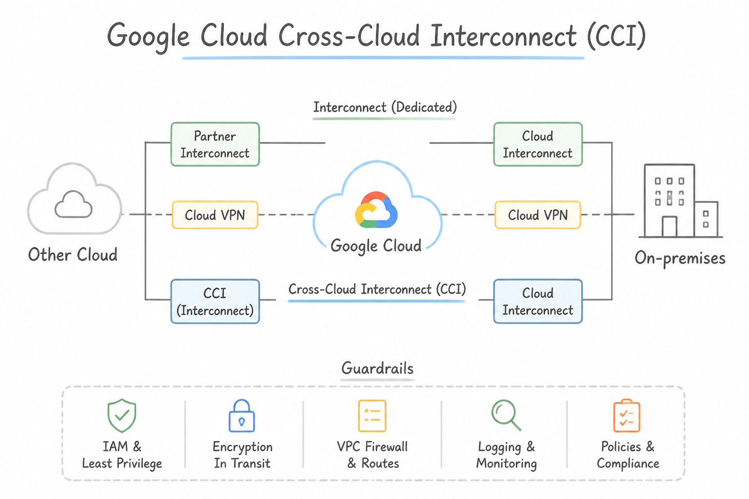
CCI): For high-throughput (10 Gbps or 100 Gbps), ultra-low-latency multicloud data pipelines (e.g., BigQuery Omni, cross-cloud AI training, database replication) between Google Cloud and AWS Direct Connect, Azure ExpressRoute, OCI FastConnect, or Alibaba Express Connect, Google provisions dedicated physical fiber between the two cloud providers at a shared colocation facility—eliminating third-party carrier middlemen.
Key Implementation Patterns
- High-Bandwidth Cross-Cloud Data Transfer: Use Order Cross-Cloud Interconnect with four 10 Gbps circuits. Cross-Cloud Interconnect provides a dedicated high-bandwidth physical link specifically for multi-cloud connectivity like AWS. (Avoid alternative: VPN uses the public internet and cannot guarantee consistent 40 Gbps bandwidth or low latency.)
- Achieving 99.99% SLA on Cross-Cloud Interconnect: Use Provision four Cross-Cloud Interconnect connections: two in a primary metropolitan area and two in a secondary metropolitan area. A 99.99% SLA requires four connections distributed across two different metropolitan areas (two per metro).
- Securing Interconnect Traffic with Encryption: Use Deploy HA VPN gateways and configure them to use the Cross-Cloud Interconnect VLAN attachments. HA VPN over Cloud Interconnect provides the required IPsec encryption while utilizing the dedicated physical link. (Avoid alternative: VLAN attachments do not have a native setting to enable IPsec encryption directly.)
Key Takeaways (1.3b)
- Use Cloud VPN for lower bandwidth needs or when quick setup over the internet is acceptable.
- Use Cloud Interconnect (Dedicated or Partner) for connecting on-premises data centers to Google Cloud.
- Use Cross-Cloud Interconnect specifically for high-bandwidth, dedicated connections between Google Cloud and other clouds like AWS or Azure.
- VPC Peering is only for connecting VPCs within Google Cloud.
Consideration 1.3c: Choosing Direct Peering or Verified Peering Provider
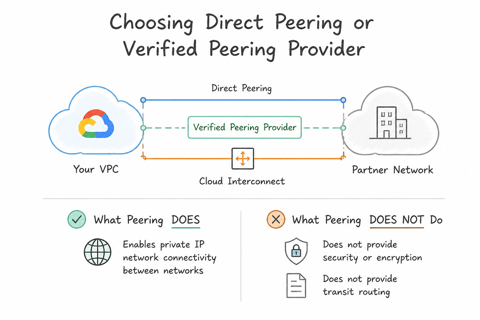
- What Peering Does (and Does NOT Do): Direct Peering and Carrier Peering (Verified Peering Provider) exist strictly to exchange BGP routes between your public ASN and Google's public edge (
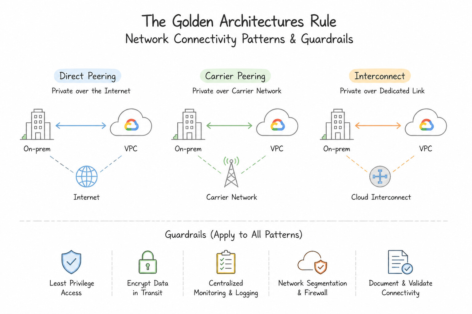
ASN 15169) to reach Google Workspace, YouTube, and public Google Cloud IPs (*.googleapis.com). - The Golden architectures Rule: Direct Peering and Verified Peering Provider sit outside Google Cloud VPCs:
- They cannot reach private RFC 1918 VM IPs inside a VPC directly.
- They provide NO financially backed SLA.
- Whenever a scenario asks for private RFC 1918 connectivity to a VPC with an SLA, immediately eliminate Direct Peering and Verified Peering Provider and choose Dedicated/Partner Interconnect or HA VPN!
- Only choose Verified Peering Provider when a customer wants public peering to Google Workspace/APIs without owning colocation presence at a Google PoP.
Key Implementation Patterns
- High-Volume Traffic Eligibility: Use Establish a Direct Peering connection. The organization meets the specific prerequisites (ASN, NOC, PoP presence) to peer directly with Google for public traffic. (Avoid alternative: Dedicated Interconnect is primarily for private VPC traffic, not general public content like YouTube.)
- Low-Volume SaaS Access: Use Register with a Verified Peering Provider to handle connectivity. Verified Peering Providers offer optimized public connectivity to Google services for customers who do not meet Direct Peering requirements. (Avoid alternative: Direct Peering requires an ASN, colocation presence, and high traffic volume, which the startup lacks.)
- Operational Overhead Reduction: Use Connect through a Verified Peering Provider. Verified Peering Providers manage the connection and NOC requirements for you, fitting the limited staff constraint. (Avoid alternative: Direct Peering requires a 24/7 NOC, which the scenario explicitly states you do not have.)
Key Takeaways (1.3c)
- Direct Peering connects your network to Google's public edge for services like YouTube, not private VPCs.
- Strict requirements for Direct Peering include owning an ASN, public IPs, a 24/7 NOC, and physical PoP presence.
- Carrier Peering is the alternative if you need public peering but lack the physical infrastructure or operational requirements.
- Cloud Interconnect is for private internal addressing (RFC 1918), not public internet peering.
Consideration 1.3d: Designing HA and DR connectivity with regional/global dynamic routing
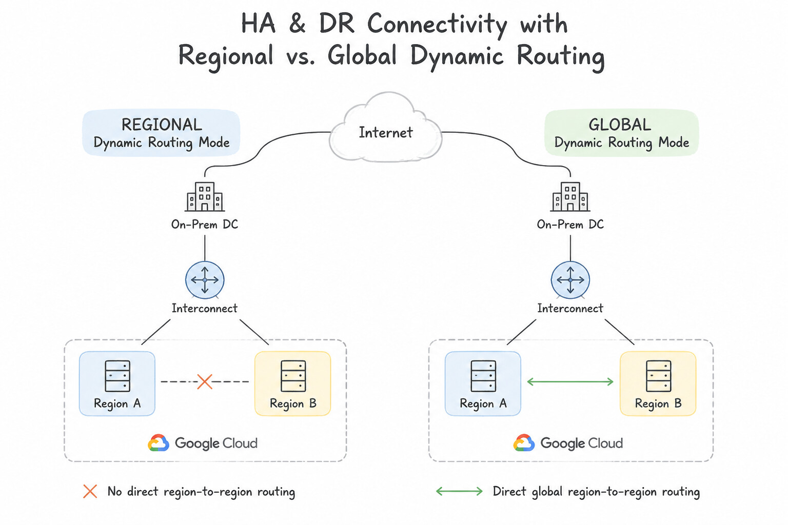
REGIONALvs.GLOBALDynamic Routing Mode:- In
REGIONALmode (default), a Cloud Router inus-east1only advertisesus-east1subnets to on-premises and only programs learned on-premises routes for VMs inus-east1. If theus-east1Interconnect fails, VMs inus-east1cannot fail over through the backup Interconnect inus-west1! - Switching the VPC to
GLOBALdynamic routing mode allows every Cloud Router in the VPC to advertise all subnets across all regions and share learned on-premises routes globally across the entire VPC. - Preventing Suboptimal Hairpin Routing (
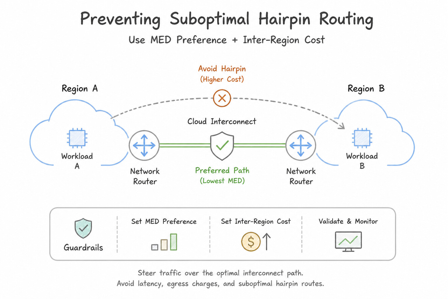
MED& Inter-Region Cost): WhenGLOBALdynamic routing is enabled with Interconnects in bothus-east1andeurope-west1, Google Cloud automatically adds an inter-region cost to learned MED values (or usesSTANDARDbest path selection) sous-east1VMs prefer the localus-east1Interconnect under normal operation and only fail over toeurope-west1if both local attachments go down.
Key Implementation Patterns
- Achieving 99.99% SLA with Dedicated Interconnect: Use Provision four dedicated connections across two metropolitan areas. In each area, connect two dedicated connections to different edge availability domains. A 99.99% SLA requires four connections: two pairs across two different metropolitan areas.
- Global Dynamic Routing for Cross-Region Failover: Use Configure the VPC network dynamic routing mode to Global. Global dynamic routing allows a Cloud Router to advertise subnets from all regions to on-premises networks. (Avoid alternative: VLAN attachments and Cloud Routers must exist in the same region.)
- Configuring Active/Passive Failover with BGP MED: Use Update the BGP sessions to advertise a lower Multi-Exit Discriminator (MED) value for the Interconnect and a higher MED value for the VPN. Lower MED values indicate a preferred path in BGP. Setting a lower MED on the Interconnect makes it the primary route.
Key Takeaways (1.3d)
- Dedicated Interconnect offers 99.9% and 99.99% SLA tiers.
- 99.9% SLA requires two connections in one metro (redundant domains).
- 99.99% SLA requires four connections across two metros (two per metro).
- Redundancy across metros is essential for disaster recovery and high availability.
Consideration 1.3e: Accessing multiple VPCs from on-prem (Shared VPC, peering, NCC)
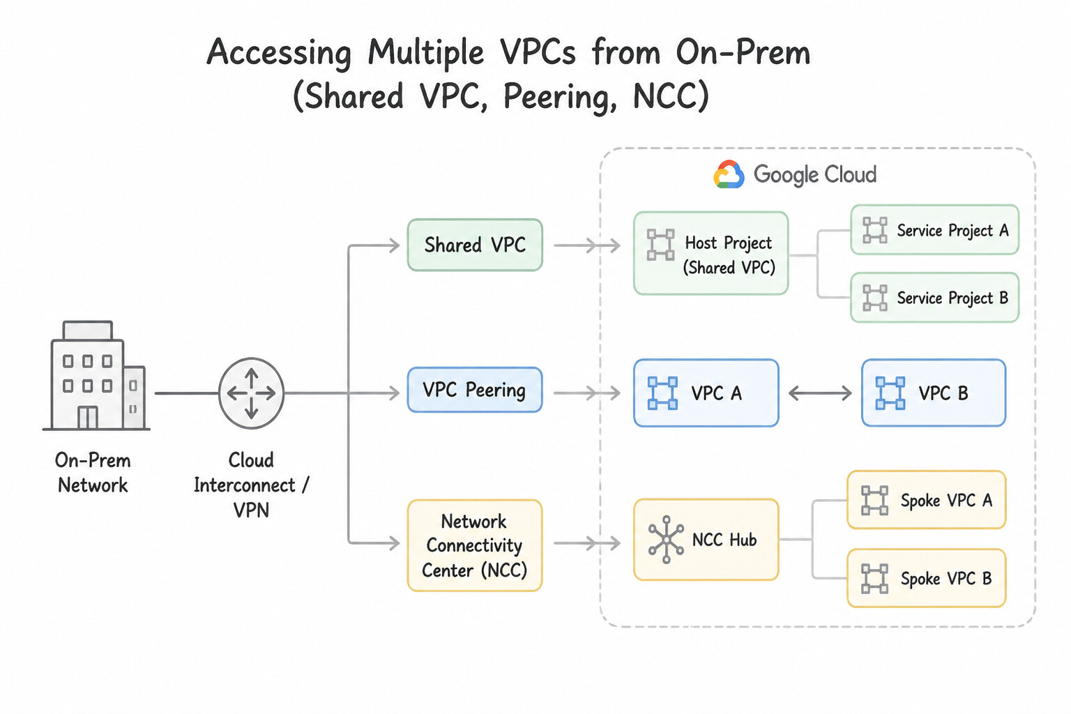
When on-premises users must reach workloads spread across multiple projects or VPCs over a single set of Interconnects/VPNs:
- Best Option (Same Trust Domain):
Shared VPC: Terminate VLAN attachments / HA VPN tunnels directly in the Shared VPC Host Project. Every Service Project shares the same underlying VPC routing table natively—zero peering limits and zero transitivity issues! - Best Option (Multiple Separate VPCs at Scale):
Network Connectivity Center (NCC): Attach the Interconnect VLAN attachments / HA VPN tunnels as NCC Hybrid Spokes and attach the workload VPCs as NCC VPC Spokes in the same NCC Hub. All VPC spokes dynamically learn the hybrid routes and vice versa! - Small Scale (Up to 25 Directly Peered Spoke VPCs):
VPC Network Peeringwith Custom Routes: Peer theTransit-VPC(which holds the Cloud Router) directly withSpoke-VPC, enable--export-custom-routesonTransit-VPCand--import-custom-routesonSpoke-VPC, and addSpoke-VPC's subnet CIDR as a Custom Route Advertisement onTransit-VPC's Cloud Router.
Key Implementation Patterns
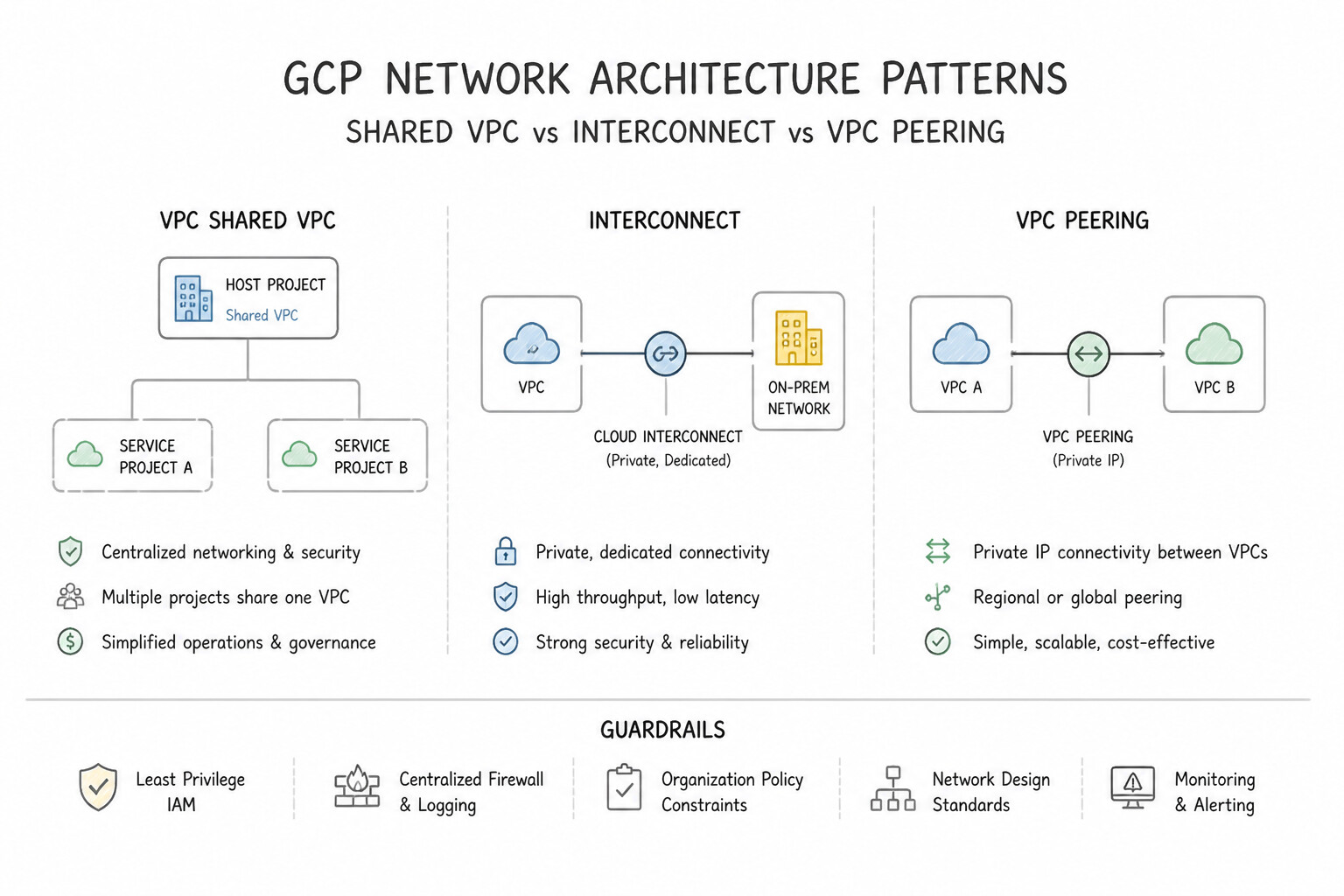
- Shared VPC for Centralized Hybrid Connectivity: Use Configure a Shared VPC. Create a host project containing the VLAN attachments and attach the 50 projects as service projects. Shared VPC allows service projects to share hybrid connectivity resources (like VLAN attachments) located in a central host project.
- VPC Network Peering Transitivity Limitations: Use Configure the Hub VPC as a Shared VPC host project and attach the Spoke project as a service project. Shared VPC allows resources in service projects to use the host project's network topology, including VPN connections, bypassing peering limitations.
- Network Connectivity Center (NCC) Implementation: Use Deploy a Network Connectivity Center (NCC) hub and add the VPCs and the hybrid connection as spokes. NCC provides a managed hub-and-spoke model that enables transitive connectivity between multiple VPCs and on-premises networks.
Key Takeaways (1.3e)
- Shared VPC is the primary tool for centralizing network administration across an organization.
- Shared VPC allows multiple service projects to leverage a single hybrid connection (Interconnect or VPN) located in the host project.
- Reducing the number of physical or logical connections (VLAN attachments) reduces both cost and complexity.
- VPC Network Peering is non-transitive; it does not propagate routes from a VPN to a peered VPC.
Consideration 1.3f: Private access to Google services like Vertex AI using PSC
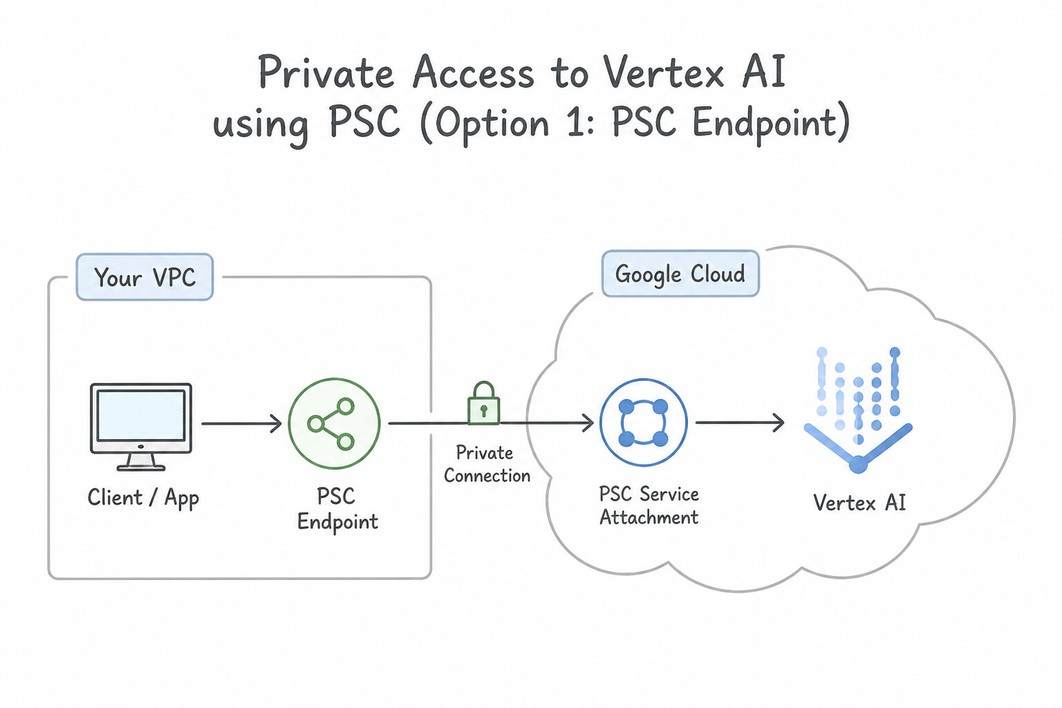
- Option 1 — Private Service Connect (
PSC) Endpoint for Google APIs (Recommended for Granular Routing & Naming): - Create a global internal IP address (e.g.,
10.100.0.1or198.18.0.1) and a PSC Forwarding Rule targeting theall-apisorvpc-scbundle (p.googleapis.com). - Advertise that single
/32IP to on-premises via Cloud Router Custom Route Advertisement, and map custom DNS records (aiplatform-psc.p.googleapis.comor*.googleapis.com) to that IP. - Option 2 — Private Google Access (
PGA) Virtual VIPs: - Advertise
199.36.153.8/30(private.googleapis.com) or199.36.153.4/30(restricted.googleapis.com) via Cloud Router Custom Route Advertisement over BGP, and configure on-premises DNS to CNAME*.googleapis.comtoprivate.googleapis.com.orrestricted.googleapis.com.. - Vertex AI Custom Endpoints / Workbench / Pipelines: Use Private Service Connect (
PSC) interfaces/endpoints for Vertex AI Online Prediction endpoints and Workbench instances so on-premises clients can invoke predictions over private IPs without transitive peering bottlenecks.
Key Implementation Patterns
- Enabling Hybrid Connectivity to PSC Endpoints: Use Enable global access on the Private Service Connect endpoint configuration. Global Access is required on PSC endpoints to allow connectivity from on-premises networks. (Avoid alternative: Advertising the IP is not sufficient; the endpoint must be configured to accept hybrid traffic.)
- Route Advertisement for PSC in Hybrid Networks: Use Update the Cloud Router BGP session to add a custom route advertisement for the PSC endpoint IP address. You must explicitly advertise the PSC endpoint IP address via BGP on Cloud Router so the on-premises router learns the route.
Key Takeaways (1.3f)
- Private Service Connect (PSC) endpoints are regional by default.
- To access a PSC endpoint from on-premises (via VPN or Interconnect), you must enable Global Access.
- Global Access also enables cross-region access within the VPC.
- Firewall rules do not substitute for enabling Global Access on the endpoint.
Consideration 1.3g: Accessing managed services via PSC or VPC Peering
- The Classic
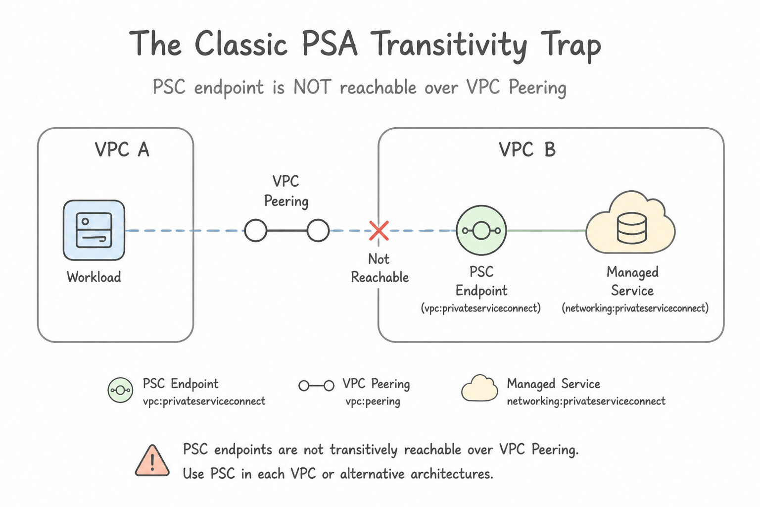
PSATransitivity Trap: When you deploy Cloud SQL, Memorystore, or Vertex AI with Private Services Access (PSA), Google creates a separate Google-owned tenant VPC and peers it with yourConsumer-VPC. If an on-premises server connects toConsumer-VPCvia Cloud Interconnect/VPN: - By default, the PSA peering connection only exchanges local subnet routes—so on-premises traffic to the Cloud SQL IP (
10.240.0.5) is blackholed! - Fix 1 (PSA Custom Route Export): Run
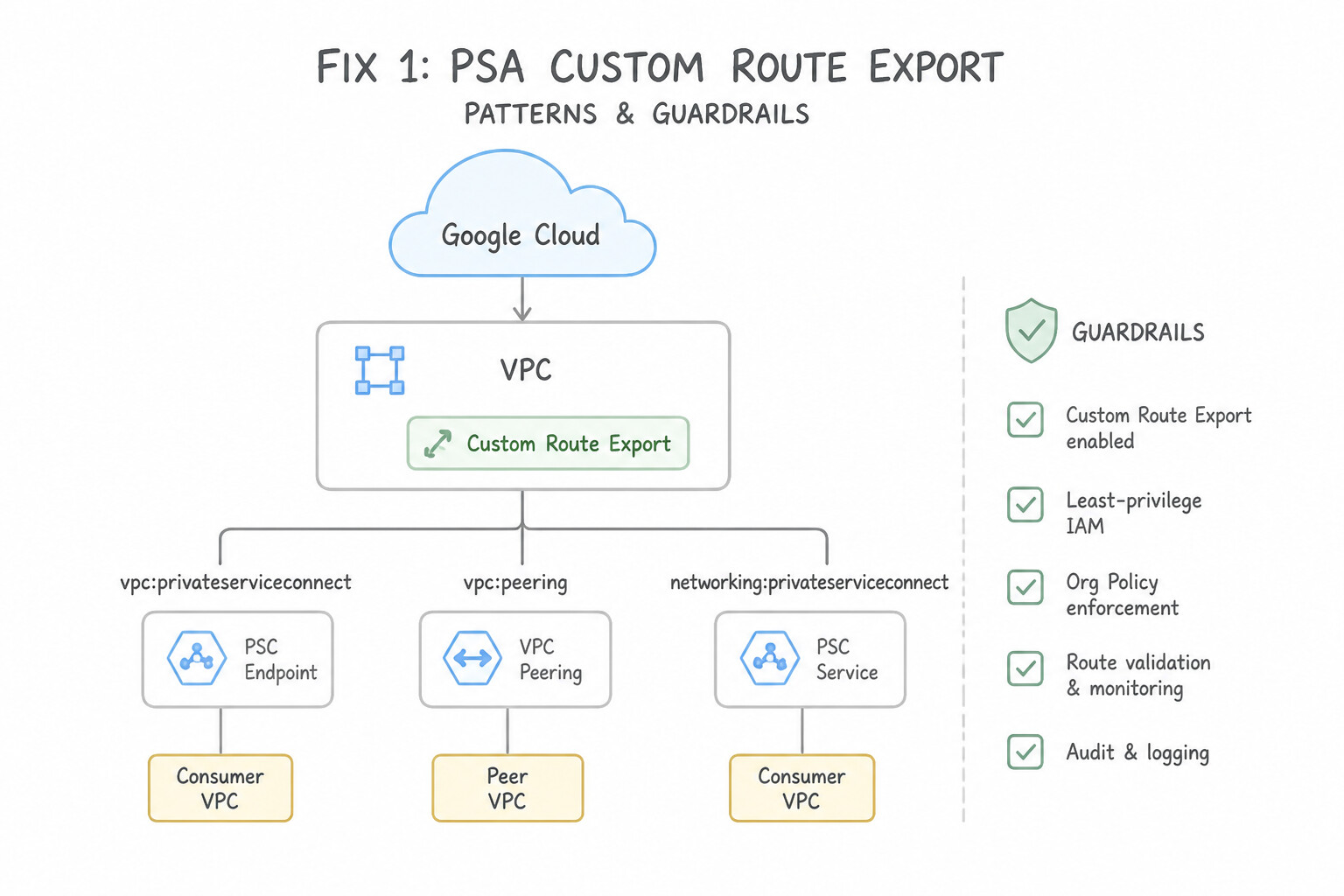
gcloud services vpc-peerings update --service=servicenetworking.googleapis.com --network=CONSUMER_VPC --export-custom-routessoConsumer-VPCexports its learned on-premises BGP routes into the Cloud SQL tenant VPC, AND advertise the PSA allocated range fromConsumer-VPC's Cloud Router to on-premises. - Fix 2 (Modern Best Practice —
PSC): Deploy the managed service (Cloud SQL, AlloyDB, Memorystore, Vertex AI) with a Private Service Connect (PSC) endpoint directly insideConsumer-VPC(or an NCC VPC Spoke with PSC propagation enabled!). Because the PSC endpoint is a local IP inside your VPC, on-premises hosts reach it immediately with zero transitive peering workarounds!
Key Implementation Patterns
- Handling Overlapping CIDR Ranges in Mergers: Use Deploy Private Service Connect to publish the application in the subsidiary's network and consume it in your network. Private Service Connect allows access to services across VPCs with overlapping IP ranges by exposing the service via a local endpoint.
- Scaling SaaS Provider Connectivity: Use Publish your application as a service using Private Service Connect. Private Service Connect scales to thousands of consumers and handles overlapping IP addresses, making it ideal for SaaS. (Avoid alternative: VPC Network Peering has a strict connection limit (quota) far below 500 and requires non-overlapping IP addresses.)
- Accessing Google APIs from On-Premises: Use Create a Private Service Connect endpoint for Google APIs using an internal IP address and advertise this IP to the on-premises network. PSC allows you to assign a specific internal IP from your subnet to front Google APIs. (Avoid alternative: Private Google Access uses Google-owned VIPs, not a specific internal IP from your VPC.)
Key Takeaways (1.3g)
- VPC Network Peering requires non-overlapping IP address ranges.
- Private Service Connect (PSC) allows service consumption across VPCs regardless of IP overlap.
- PSC is ideal for one-way access to specific services (Producer-Consumer model).
- Avoid complex VPN/NAT setups for single-service access if a managed service option exists.
Consideration 1.3h: Designing non-overlapping IP space across environments
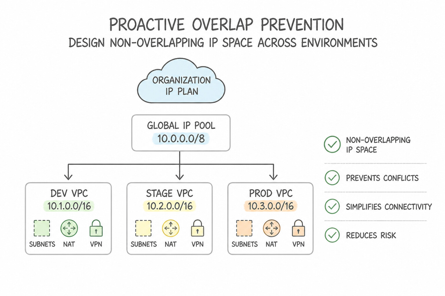
- Proactive Overlap Prevention: Use Network Connectivity Center Internal Ranges (
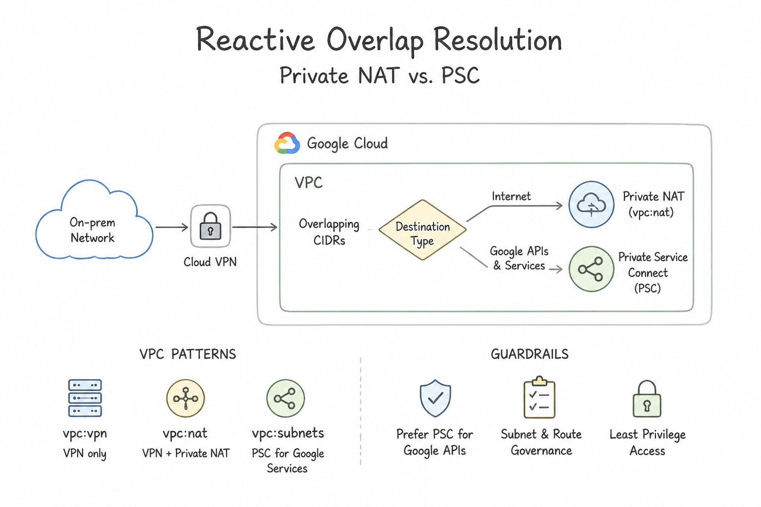
InternalRangewithPEERINGorFOR_SELFusage) to reserve blocks across cloud projects and lock out on-premises CIDR ranges so cloud teams cannot accidentally create conflicting subnets. - Reactive Overlap Resolution (
Private NATvs.PSC): - When an acquired company or legacy data center shares the exact same
10.0.0.0/8range as your VPC and re-IPing is impossible: - Use Private Service Connect (
PSC) for specific application-to-service communication ( consumer PSC Endpoint → producer Service Attachment). - Use Private NAT on an NCC Hub (requires creating a dedicated non-overlapping
--purpose=PRIVATE_NATsubnet) so VMs in the VPC spoke have their source IP NATed before traversing the NCC Hybrid Spoke to on-premises.
Key Implementation Patterns
- Merger and Acquisition Network Integration: Use Configure a Cloud VPN connection. Implement Network Address Translation (NAT) to translate the overlapping IP addresses to a non-overlapping range. NAT is required to route traffic between networks with overlapping IP ranges over Cloud VPN.
- RFC 6598 Shared Address Space Usage: Use Configure the VPC subnets using the 100.64.0.0/10 address range. RFC 6598 (100.64.0.0/10) is supported by Google Cloud and allows for non-overlapping private addressing when RFC 1918 space is exhausted. (Avoid alternative: Reusing 10.0.0.0/8 creates an IP overlap conflict, and Cloud NAT is primarily for internet access, not for resolving internal hybrid IP conflicts without NAT.)
- GKE Pod Range Planning in Hybrid Networks: Use Select IP address ranges that do not overlap with either 10.1.1.0/24 or 10.2.0.0/16. VPC-native clusters require unique, non-overlapping IP ranges for Pods and Services to route traffic to on-premises networks. (Avoid alternative: Overlapping IP ranges prevent traffic from routing correctly across the VPN tunnel.)
Key Takeaways (1.3h)
- VPC Network Peering cannot function if there is any IP address overlap between networks.
- Cloud VPN with NAT is a standard pattern for connecting networks with overlapping IP spaces during migrations or mergers.
- Dedicated Interconnect takes longer to provision than Cloud VPN and does not inherently solve Layer 3 IP conflicts.
- RFC 1918 addresses (10.x, 172.16.x, 192.168.x) are standard for private networks but can run out.
Consideration 1.3i: Designing DNS peering and forwarding strategy
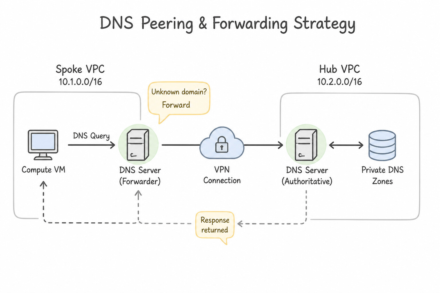
Memorize the four building blocks of enterprise hybrid DNS:
- Inbound Server Policy (
On-Premises→Cloud DNS): Enabled on the VPC; allocates an internal IP in each regional subnet where VMs/attachments exist. On-premises DNS servers configure conditional forwarders for.gcp.example.com(andgoogleapis.com) pointing to these Inbound Server Policy IPs. - Outbound Private Forwarding Zone (
Cloud DNS→On-Premises): Created in Cloud DNS foronprem.corp.; forwards queries from VPC VMs to on-premises DNS server IPs. Remember to allow ingress on on-premises firewalls from35.199.192.0/19(for Type 1 default forwarding path) or from your VPC internal range (for Type 2 private routing). - Cross-Project Binding (
Centralized Hub DNS): Bind a single Cloud DNS Private Zone (or Forwarding Zone) located in a centralNetwork-Hubproject directly to up to 50+ authorized VPCs across different projects within the same Organization—avoiding DNS Peering hops when full zone visibility is desired. - DNS Peering (
Namespace Delegation Across Projects/Orgs): Forwards queries for a specific domain namespace from a consumer VPC to a producer VPC's DNS config—Crucially, DNS Peering is NOT transitive! IfSpoke-VPCDNS-peers toHub-VPC, andHub-VPChas a Forwarding Zone to on-premises, verify whether direct Cross-Project Binding of the Forwarding Zone toSpoke-VPCis cleaner.
Key Implementation Patterns
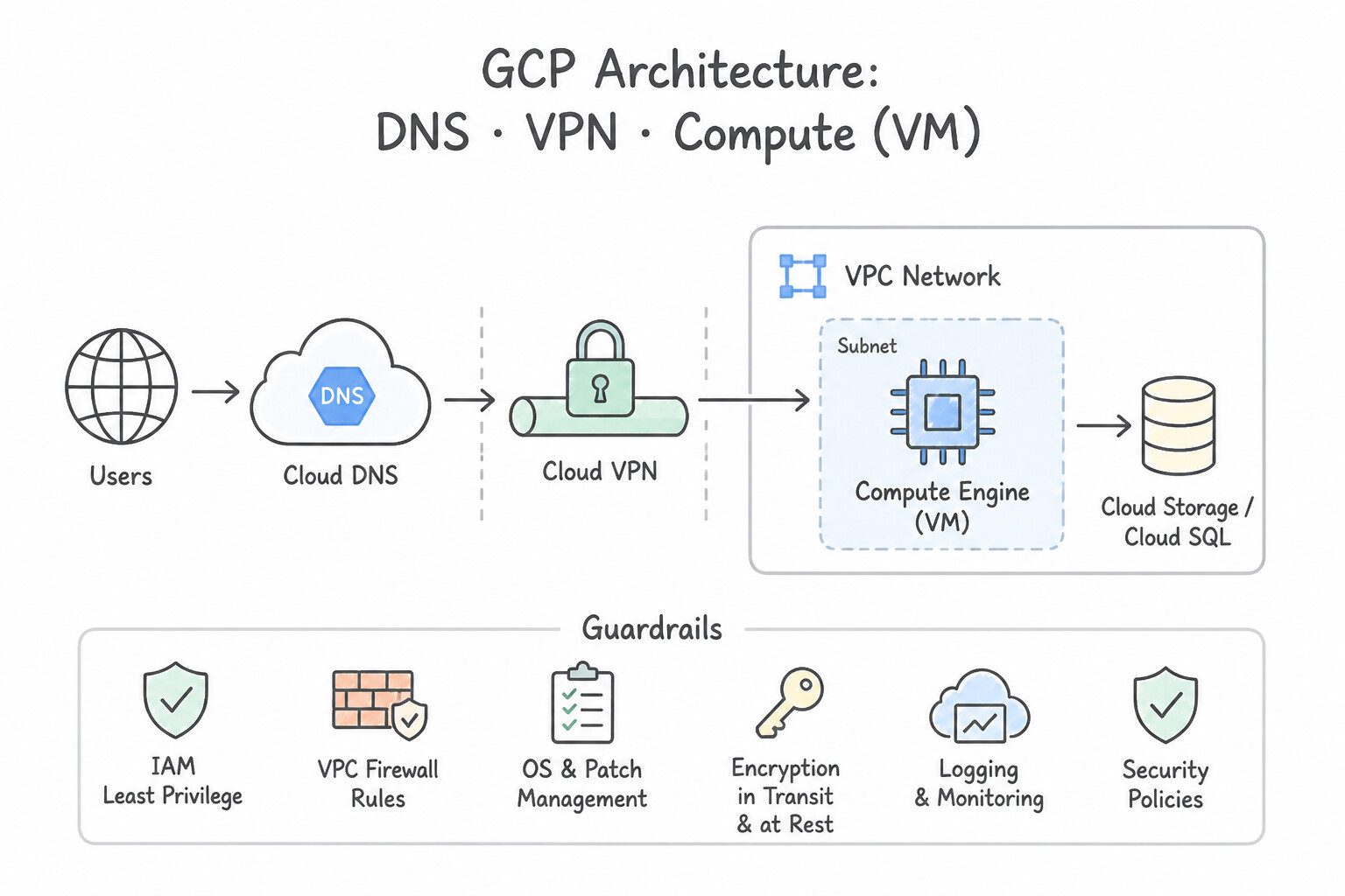
- Configuring Outbound DNS Resolution to On-Premises: Use Create a private Cloud DNS zone for corp.local with the zone type set to Forwarding, and add the on-premises DNS server IP addresses as targets. A forwarding zone directs DNS queries for a specific suffix to external nameservers, allowing resolution of on-premises resources.
- Enabling On-Premises Resolution of GCP Resources: Use Configure a Cloud DNS inbound server policy. Update the on-premises DNS servers to forward queries for the Google Cloud domain to the inbound forwarding proxy IP addresses. An inbound server policy creates entry points (proxy IP addresses) in your VPC that allow on-premises systems to resolve Cloud DNS records.
- Centralized DNS in a Hub-and-Spoke Topology: Use Create a Cloud DNS peering zone in the spoke VPC. Set the target network to the hub VPC. A Cloud DNS peering zone allows the spoke VPC to query the hub VPC's name resolution configuration, including its forwarding paths to on-premises.
Key Takeaways (1.3i)
- Forwarding Zones are used for outbound DNS resolution (GCP querying On-Prem).
- Inbound Server Policies are used for inbound DNS resolution (On-Prem querying GCP).
- DNS Peering is strictly for communication between Google Cloud VPC networks.
- Avoid manual static entries for dynamic hybrid environments to prevent synchronization issues.
Consideration 1.3j: Determining correct MTU sizing for hybrid connections
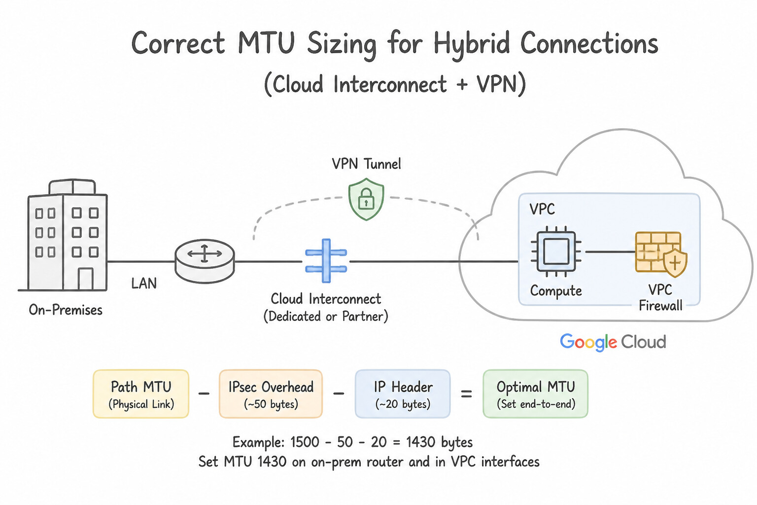
- Cloud Interconnect (Unencrypted Dedicated or Partner): Supports MTU values of
1440,1460,1500, or8896(Jumbo Frames). The VLAN attachment MTU must match both the on-premises router subinterface MTU and the attached Google Cloud VPC MTU! - Cloud HA VPN (Over Internet): Supports
1460bytes (default) or1500bytes payload MTU (provided the underlying internet path supports jumbo outer IPsec packets; otherwise1460is safest, with TCPMSSclamped to1420bytes). - HA VPN over Cloud Interconnect (Encrypted Interconnect): Because the outer IPsec ESP packet must fit inside the underlying VLAN attachment MTU, the encrypted VLAN attachment is configured to
1440or1500bytes, and the inner HA VPN tunnel MTU is set accordingly (1440bytes default).
Key Implementation Patterns
- Diagnosing MTU Mismatches in Cloud VPN: Use Configure the on-premises VPN gateway to clamp the TCP MSS to 1360 bytes. Clamping TCP MSS accounts for IPsec header overhead, ensuring packets fit within the VPN tunnel MTU. (Avoid alternative: Google Cloud VPCs use an MTU of 1460 bytes; increasing this does not account for VPN encapsulation overhead.)
- Enabling Path MTU Discovery (PMTUD): Use Create an ingress firewall rule allowing ICMP Type 3, Code 4 traffic from on-premises ranges. PMTUD requires ICMP Type 3, Code 4 (Fragmentation Needed) to inform senders when packets are too large. (Avoid alternative: ICMP Type 8 is for Ping requests, not for MTU negotiation messages.)
- Optimizing MTU for Dedicated Interconnect: Use Update the VPC network MTU to 1500 bytes. Stop and start the virtual machine (VM) instances. The default VPC MTU is 1460 bytes, causing fragmentation for 1500-byte on-premises traffic. You must increase the VPC MTU to 1500 bytes and restart VMs to apply the change.
Key Takeaways (1.3j)
- Google Cloud VPC default MTU is 1460 bytes.
- VPN tunnels add encapsulation overhead, effectively reducing the available payload size.
- Symptoms like 'SSH connects but freezes on output' or 'HTTP loads forever' suggest MTU issues.
- TCP MSS clamping is the preferred network-level fix to ensure packets fit within the tunnel MTU.
Consideration 1.3k: Understanding encryption options (MACsec, HA VPN over Interconnect)
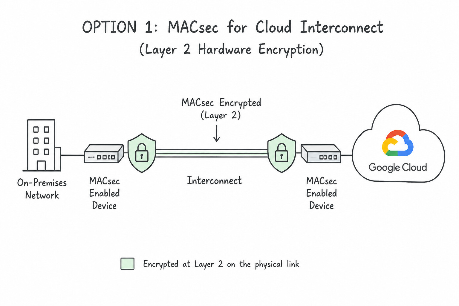
When a workload scenario requires encrypting traffic over Cloud Interconnect, compare these two native architectures:
- Option 1 —
MACsecfor Cloud Interconnect (Layer 2 Hardware Encryption): - Supported On: Dedicated Interconnect ONLY (10 Gbps and 100 Gbps physical ports directly connected to Google edge routers; not supported on Partner Interconnect because the carrier switch sits in the middle at Layer 2).
- Performance & Overhead: IEEE
802.1AEhardware-accelerated point-to-point encryption on the physical fiber link with near-zero throughput penalty (full 10G/100G line rate) and no IPsec tunnel bandwidth limits. - Option 2 —
HA VPN over Cloud Interconnect(Layer 3 IPsec Encryption): - Supported On: Both Dedicated Interconnect AND Partner Interconnect.
- How It Works: You provision a VLAN attachment with
--encryption=IPSEC(which allocates a dedicated regional internal IP range) and deploy an HA VPN Gateway bound to that VLAN attachment. - Performance & Scaling: Provides end-to-end FIPS 140-2 validated IPsec encryption into the VPC, capped at 3 Gbps (or 250,000 PPS) per HA VPN tunnel (scale total encrypted bandwidth by deploying multiple HA VPN gateways/tunnels across the VLAN attachment).
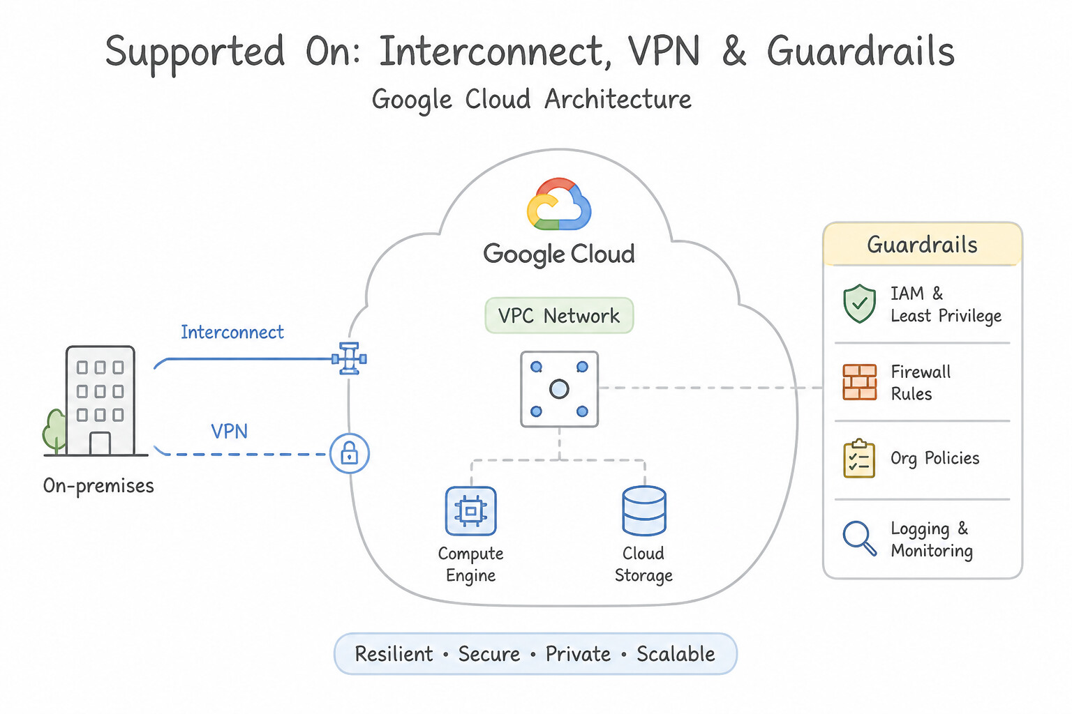
Key Implementation Patterns
- High-Throughput L2 Encryption for Finance: Use Provision a Dedicated Interconnect connection and enable MACsec encryption. MACsec provides Layer 2 encryption at line-rate speeds on Dedicated Interconnect, satisfying the requirement for 100 Gbps encryption without IPsec latency.
- Aggregating Bandwidth with Encryption: Use Create multiple VPN tunnels and use Equal-Cost Multi-Path (ECMP) routing. Use ECMP across multiple tunnels to aggregate bandwidth beyond the 3 Gbps per-tunnel limit. (Avoid alternative: MTU adjustments do not increase the maximum cryptographic throughput cap of a single tunnel (3 Gbps).)
Key Takeaways (1.3k)
- MACsec provides Layer 2 encryption for Dedicated Interconnect, securing traffic between the on-premises router and Google's edge router.
- MACsec is preferred over IPsec when low latency and line-rate performance (e.g., 100 Gbps) are required.
- IPsec operates at Layer 3 and introduces processing overhead and latency compared to MACsec.
- A single Cloud VPN tunnel is limited to approximately 3 Gbps throughput.
Quick Decision Cheat Sheet (Subsection 1.3)
If the Scenario Requires... | Choose This Google Cloud Pattern | Avoid This Common Mistake |
|---|---|---|
"Need 500 Mbps – 2 Gbps private link + data center is NOT in a Google colocation facility + requires SLA" | Partner Interconnect (with redundant VLAN attachments) | Dedicated Interconnect (requires colocation & min 10 Gbps) or Direct Peering (no VPC access, no SLA) |
"On-premises in us-east1 cannot reach VPC subnets in europe-west1 over a working Interconnect" | Change VPC Dynamic Routing Mode from REGIONAL to GLOBAL | Creating static routes on Cloud Router or adding a second VPC |
"On-premises DNS forwarders can't resolve GCP private zones over HA VPN" | Enable Cloud DNS Inbound Server Policy on the VPC and point on-premises forwarders to the regional policy IPs | Creating an Outbound Forwarding Zone (wrong direction) or DNS Peering |
"Cloud DNS Outbound Forwarding Zone queries to on-premises DNS servers time out" | Allow ingress from 35.199.192.0/19 on on-premises firewalls AND advertise/route 35.199.192.0/19 over VPN/Interconnect | Allowing only the VPC primary subnet CIDR (Type 1 forwarding uses 35.199.192.0/19 source IPs) |
"Access Vertex AI / Cloud Storage privately from on-premises over Interconnect without public IPs" | PSC Endpoint for Google APIs (or PGA 199.36.153.8/30 / 199.36.153.4/30) + Cloud Router Custom Route Advertisement | Enabling PGA alone without advertising the route over BGP or configuring hybrid DNS |
"Line-rate Layer 2 encryption on 100 Gbps Dedicated Interconnect" | MACsec for Cloud Interconnect | Classic VPN or Cloud NAT |
Further Reading (Subsection 1.3)
- Dedicated Interconnect 99.99% Availability — Documentation describing the topology required for 99.99% availability, specifically detailing the need for four connections across two metros.
- MACsec for Dedicated Interconnect — Overview of MACsec functionality, benefits (Layer 2 protection), and how it differs from IPsec VPN.
- Cross-Cloud Interconnect overview — Explains how Cross-Cloud Interconnect enables high-bandwidth, dedicated connectivity to other cloud service providers.
- Cloud Interconnect SLA — Details the specific topology requirements (number of connections and locations) needed to qualify for 99.9% and 99.99% SLAs.
- HA VPN over Cloud Interconnect — Documentation explaining how to deploy HA VPN gateways over Cloud Interconnect to encrypt traffic.
- VPC Network Peering — Explains the difference between Direct Peering and Carrier Peering, and lists the requirements for establishing a Direct Peering connection.
Book TOC · Previous · Chapter 1 of 8 · Next
AwesomeGCP.com Learning
The approach taken is a question-led learning approach: you explore realistic project scenarios where you need to make decisions or take actions to achieve business goals within specific constraints. Instead of passive learning, you are challenged to think and work through the options to master the Professional Cloud Network Engineer (PCNE) certification!