Book TOC · Previous · Chapter 5 of 8 · Next
Chapter 5: Hybrid & Multicloud Interconnectivity: Cloud Interconnect, HA VPN, Cloud Router BGP & NCC
Chapter Focus: Dedicated vs. Partner vs. Cross-Cloud Interconnect, 99.9% vs. 99.99% SLA topologies, MACsec, HA VPN, Cloud Router BGP (MED, AS-Path prepending, Custom Advertised Routes, BFD), and Hybrid NCC spokes.
Subsection 4.1: Configuring Cloud Interconnect
The Big Picture
When enterprise architects design physical hybrid connectivity to Google Cloud, two failure patterns dominate post-mortem reviews: single-metro / single-edge-availability-domain correlation failures that violate the 99.99% SLA, and unencrypted Layer 2/3 transit that fails strict regulatory audits (PCI-DSS, HIPAA, Defense/Financial mandates). Ordering two 10 Gbps Dedicated Interconnect circuits in the same colocation facility and plugging both into Edge Availability Domain 1 (zone1) gives you zero SLA (not even 99.9%) during Google scheduled maintenance on that Edge Availability Domain. Achieving the 99.99% SLA requires a strict four-circuit architecture split across two distinct metropolitan areas (metros) and two distinct Edge Availability Domains per metro, paired with Global Dynamic Routing on the VPC.
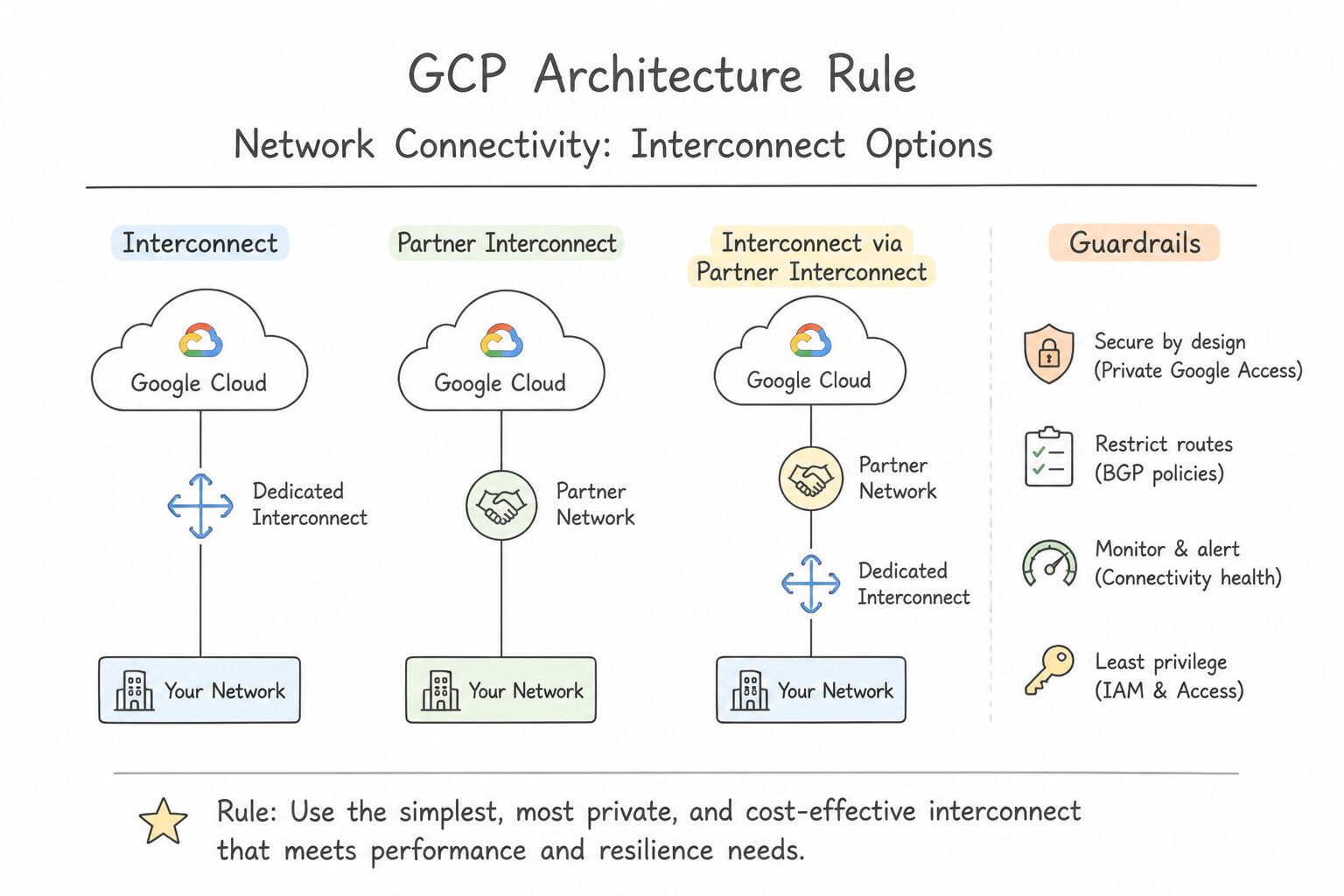
Furthermore, Cloud Interconnect traffic is not encrypted by default over the physical fiber unless you configure either MACsec for Cloud Interconnect (Layer 2 hop-by-hop link encryption on Dedicated Interconnect) or HA VPN over Cloud Interconnect (Layer 3 end-to-end IPsec encryption terminated on encrypted VLAN attachments). Understanding the exact operational boundaries between Dedicated Interconnect (10G/100G physical cross-connects with LOA-CFA), Partner Interconnect (50 Mbps to 50 Gbps Layer 2 vs. Layer 3 service provider circuits), and Cross-Cloud Interconnect (direct physical multicloud links to AWS, Azure, OCI, and Alibaba Cloud) is foundational for Section 4 of the Architecture Stack.
Consideration 4.1a: Creating Dedicated Interconnect and VLAN attachments
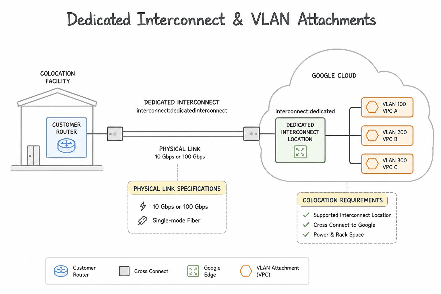
- Physical Link Specifications & Colocation Requirements:
- Dedicated Interconnect provides a direct physical fiber cross-connect between your on-premises router and Google's peering edge router inside a shared colocation facility.
- Supported Link Speeds:
- 10 Gbps links: Up to 8 x 10 Gbps links per LACP bundle (
80 Gbpsmax per connection). - 100 Gbps links: Up to 2 x 100 Gbps links per LACP bundle (
200 Gbpsmax per connection). - Provisioning Lifecycle:
- Order a Dedicated Interconnect connection in the Google Cloud Console/CLI specifying the colocation facility and Edge Availability Domain (
zone1orzone2). - Google emails a Letter of Authorization and Connecting Facility Assignment (LOA-CFA) to the technical contact.
- Send the LOA-CFA to the colocation facility vendor to run the physical single-mode fiber cross-connect.
- Google tests the physical link using light-level verification and temporary
/30test IPs (no production traffic allowed during testing) before marking the connection active. - Technical Requirements on Customer Equipment:
- Must support single-mode fiber (
10GBASE-LR1310nm or100GBASE-LR4), 802.1Q VLAN tagging, LACP (802.3ad) (required even for a single physical link!), EBGP-4 with multi-hop disabled, and IPv4 Link-Local (169.254.0.0/16) peering addresses. - VLAN Attachments (
InterconnectAttachments): - A single physical Dedicated Interconnect connection can carry multiple logical
802.1QVLAN attachments (up to 16 attachments per 10G connection, scaling higher with more links). - Each VLAN attachment connects to one Cloud Router in one VPC (or to an NCC Hub as a hybrid spoke) and can be configured with a provisioned bandwidth cap (
50 Mbpsup to50 Gbpsor100 Gbps) and an MTU of1440,1460,1500, or8896bytes (jumbo frames, provided the VPC MTU also matches).
Key Implementation Patterns
- Ordering and Provisioning Dedicated Interconnect: Use Download the Letter of Authorization - Connecting Facility Assignment (LOA-CFA) and email it to your vendor. The PROVISIONED status indicates that Google has prepared the ports and generated the LOA-CFA, which you must send to your vendor to install the cabling.
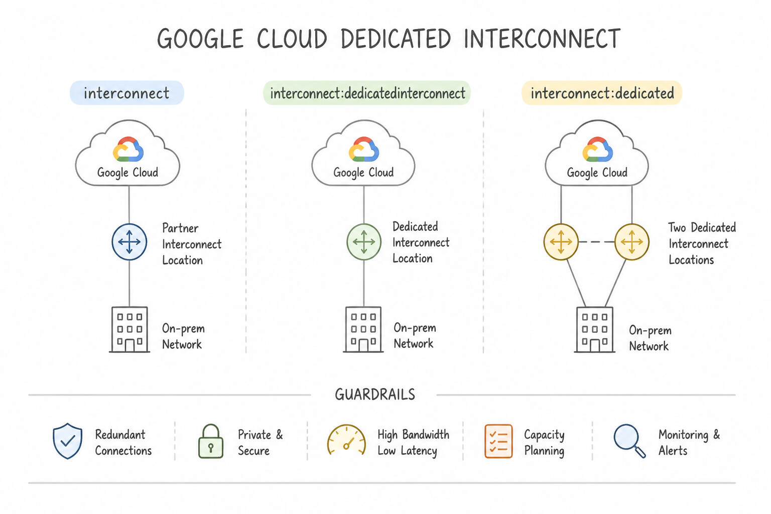
- Achieving 99.99% Availability SLA: Use Provision four dedicated connections across two different metropolitan areas. Configure two connections in each metropolitan area. The 99.99% SLA requires four connections total: two connections in one metropolitan area and two connections in a second metropolitan area.
- Configuring LACP for Bundle Aggregation: Use Configure LACP in Active mode on the on-premises router interfaces. Google Cloud requires the on-premises side of a Dedicated Interconnect to use LACP in Active mode to properly negotiate the link bundle. (Avoid alternative: Passive mode waits for the peer to initiate negotiation, which may result in the link remaining down if the peer is also waiting.)
Key Takeaways (4.1a)
- The 'PROVISIONED' status for Dedicated Interconnect means Google has allocated ports and the LOA-CFA is ready.
- The LOA-CFA (Letter of Authorization - Connecting Facility Assignment) is the mandatory document required by vendors to install physical cross-connects.
- Google does not perform the cross-connect installation; the customer must initiate this with the facility vendor.
- 99.9% SLA requires 2 connections in 1 metro (separate zones).
Consideration 4.1b: Configuring Partner Interconnect
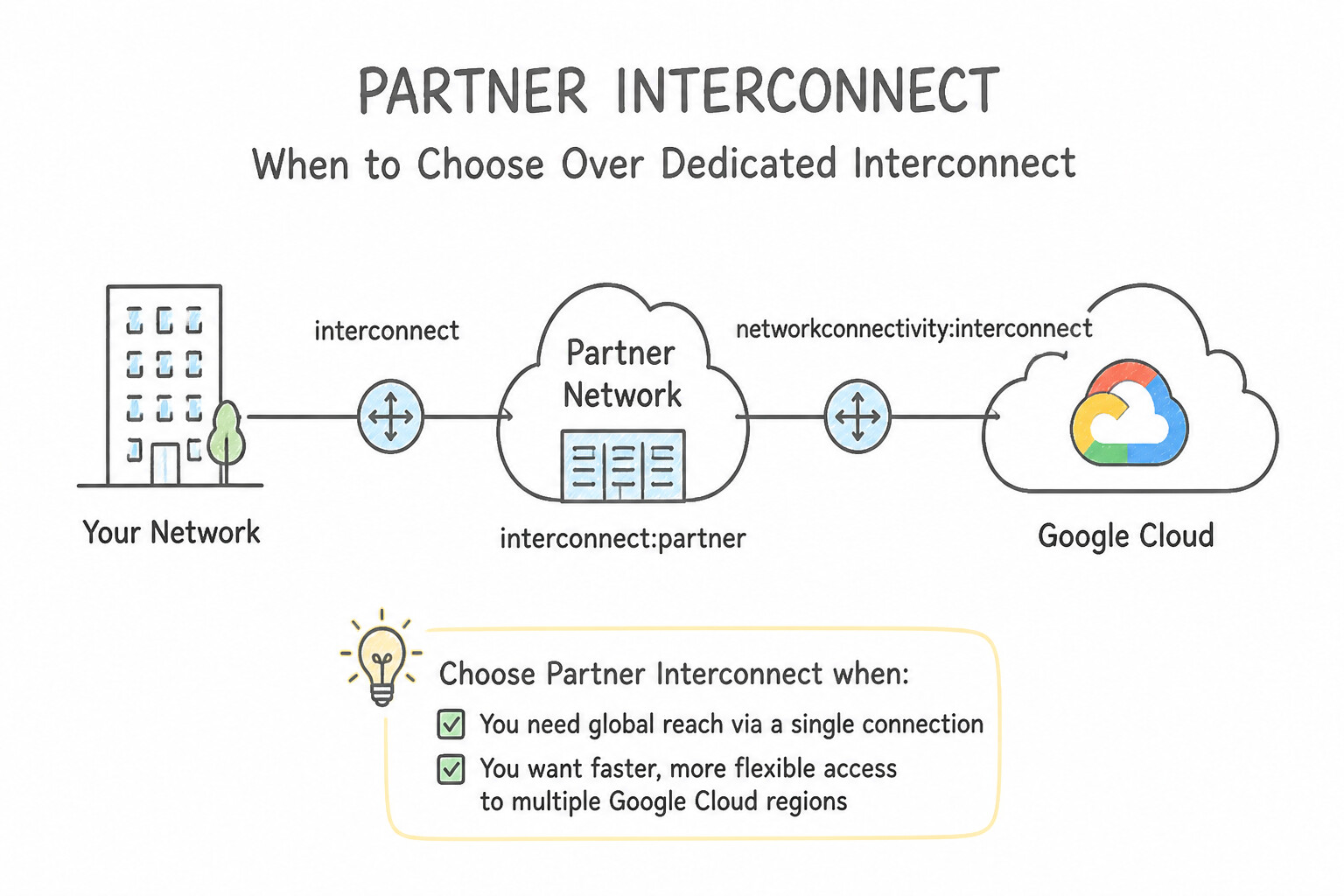
- When to Choose Partner Interconnect over Dedicated Interconnect:
- Your data center is not physically present in a Google colocation facility and you do not want to lease dark fiber to reach one, OR your bandwidth requirement is less than 10 Gbps (Partner Interconnect supports capacities from
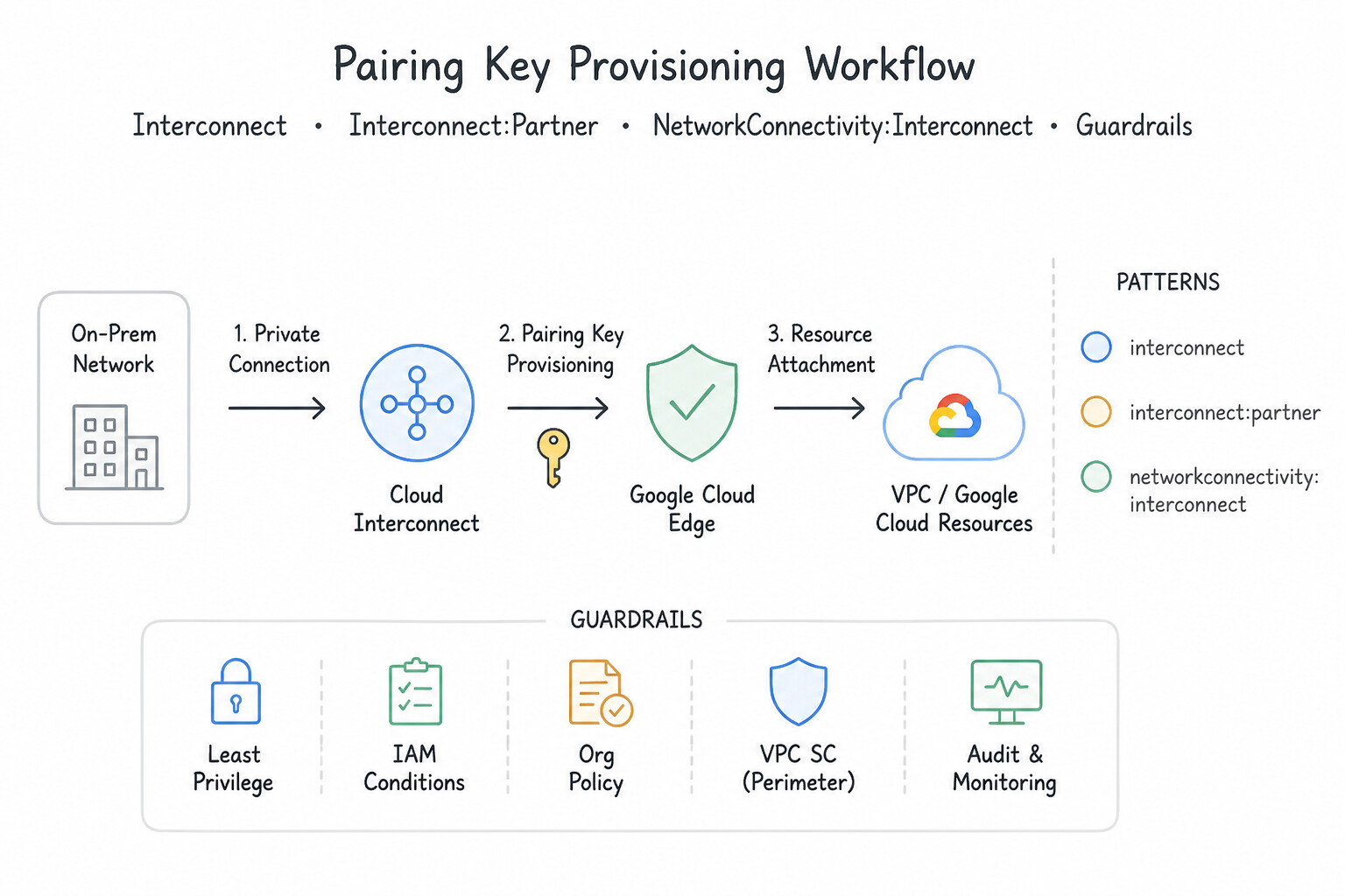
50 Mbpsto50 Gbpsper VLAN attachment). - Pairing Key Provisioning Workflow:
- Create a Partner Interconnect VLAN attachment in your VPC (choosing region, Cloud Router, and Edge Availability Domain
zone1/zone2). - Google Cloud generates a unique Pairing Key (e.g.,
7e51371e-72a3-40b5-b844-2e3efefaee59/us-central1/1). - Provide the Pairing Key to your chosen connectivity service provider (Equinix Fabric, Megaport, AT&T, Colt, Verizon, etc.), who provisions the virtual circuit on their shared trunk to Google.
- Activate the VLAN attachment in Google Cloud (or use Pre-Activate at creation time so traffic flows as soon as the provider completes provisioning).
- Layer 2 vs. Layer 3 Partner Interconnect (Key Architectural Distinction):
- Layer 2 Partner Interconnect: The service provider acts as a transparent VLAN switch (
802.1Q/ QinQ). The BGP session is established directly between YOUR on-premises router and your Google Cloud Router. You configure the BGP ASN on your on-premises router. - Layer 3 Partner Interconnect: The service provider manages the Layer 3 routing on their provider edge (PE) router. The BGP session is established between the SERVICE PROVIDER'S router and your Google Cloud Router. You must configure the Cloud Router BGP peer with the Service Provider's ASN, not your own internal ASN!
Key Implementation Patterns
- Partner Interconnect Provisioning Artifacts: Use The pairing key generated during the VLAN attachment creation. The pairing key is the unique token generated by Google Cloud that authorizes the service provider to provision the Partner Interconnect circuit. (Avoid alternative: Service account keys are for API authentication, not for provisioning network circuits with a third-party provider.)
- Achieving 99.99% Availability SLA: Use Create four VLAN attachments across two separate metros. Configure two attachments in each metro. 99.99% availability requires four attachments split between two separate metros (two in each). (Avoid alternative: Two attachments in one metro only provide 99.9% availability.)
Key Takeaways (4.1b)
- Partner Interconnect connects your on-premises network to Google Cloud through a third-party service provider.
- A Pairing Key is the unique token generated when creating a VLAN attachment.
- You must share the pairing key with the service provider to authorize and facilitate the circuit provisioning.
- Service Account keys and BGP details serve different purposes (authentication and routing, respectively) and are not used for the initial circuit handshake.
Consideration 4.1c: Configuring Cross-Cloud Interconnect
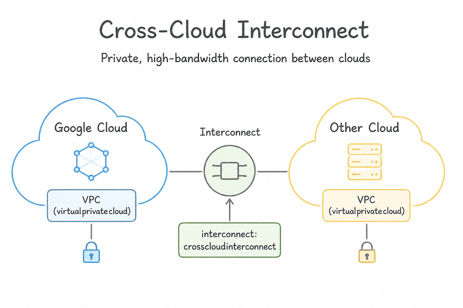
- What is Cross-Cloud Interconnect?:
- A managed physical dedicated connection (available in 10 Gbps or 100 Gbps link increments) that connects a Google Cloud VPC directly to another cloud service provider (AWS Direct Connect, Microsoft Azure ExpressRoute, Oracle Cloud Infrastructure FastConnect, or Alibaba Cloud Express Connect) inside a shared colocation facility—without requiring you to buy, rack, or manage any physical routers or third-party SD-WAN fabric in between.
- Provisioning Architecture:
- You order both a primary and redundant Cross-Cloud Interconnect port in Google Cloud specifying the target cloud provider and shared location.
- Google Cloud and the peer cloud provider (e.g., AWS or Azure) each issue LOA/connection authorizations, and Google engineers physically patch and manage the cross-connect between Google's edge routers and the peer cloud's edge routers.
- You then create VLAN attachments and Cloud Router BGP sessions in Google Cloud that peer directly with AWS Virtual Interfaces (VIFs) or Azure ExpressRoute private peering circuits.
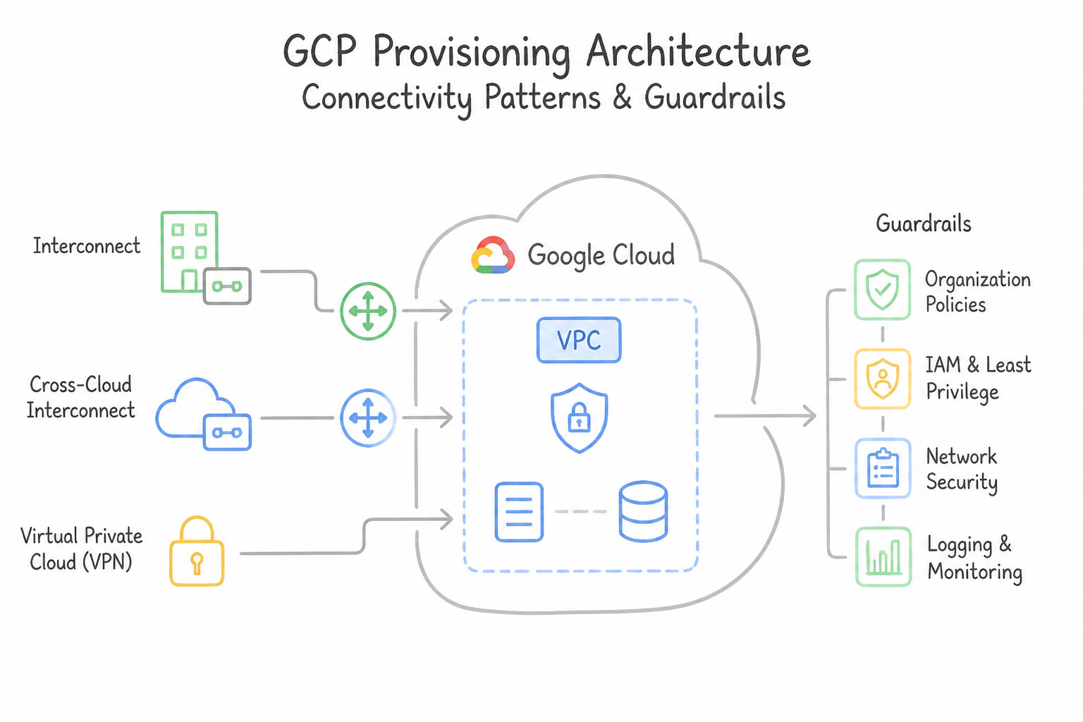
Key Implementation Patterns
- Achieving 99.99% SLA with Cross-Cloud Interconnect: Use Provision four connections total: two in one metropolitan area and two in a different metropolitan area. Ensure connections in each metro use different edge availability domains. 99.99% availability requires four connections spread across two metropolitan areas.
- Ordering Process for AWS Direct Connect Integration: Use Download the Letter of Authorization - Connecting Facility Assignment (LOA-CFA) from Google Cloud. Submit this document to AWS to order the cross-connect. You must download the LOA-CFA from Google and provide it to AWS to physically build the connection.
- Securing Layer 2 Traffic with MACsec: Use Enable MACsec on the Interconnect attachment, and configure the Connectivity Association Key (CAK) and Connectivity Association Key Name (CKN). MACsec provides the required Layer 2 encryption for Cloud Interconnect and requires configuring a CAK and CKN.
Key Takeaways (4.1c)
- Cross-Cloud Interconnect allows private traffic between Google Cloud and other clouds like AWS.
- To achieve 99.99% availability, you must use four connections.
- The four connections must be distributed: two in one metro and two in another.
- Connections within the same metro should be in different edge availability domains.
Consideration 4.1d: Configuring HA VPN over Interconnect
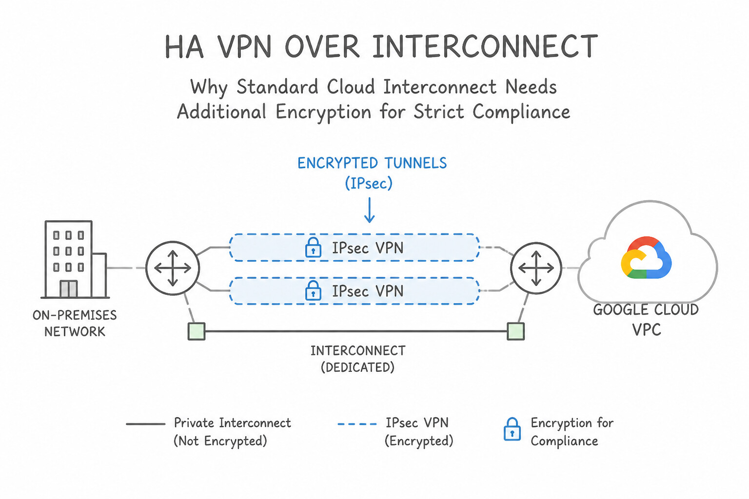
- Why Standard Cloud Interconnect Needs Additional Encryption for Strict Compliance:
- Standard Dedicated and Partner Interconnect VLAN attachments carry unencrypted plaintext IP packets over the physical circuit or provider MPLS/Ethernet backbone.
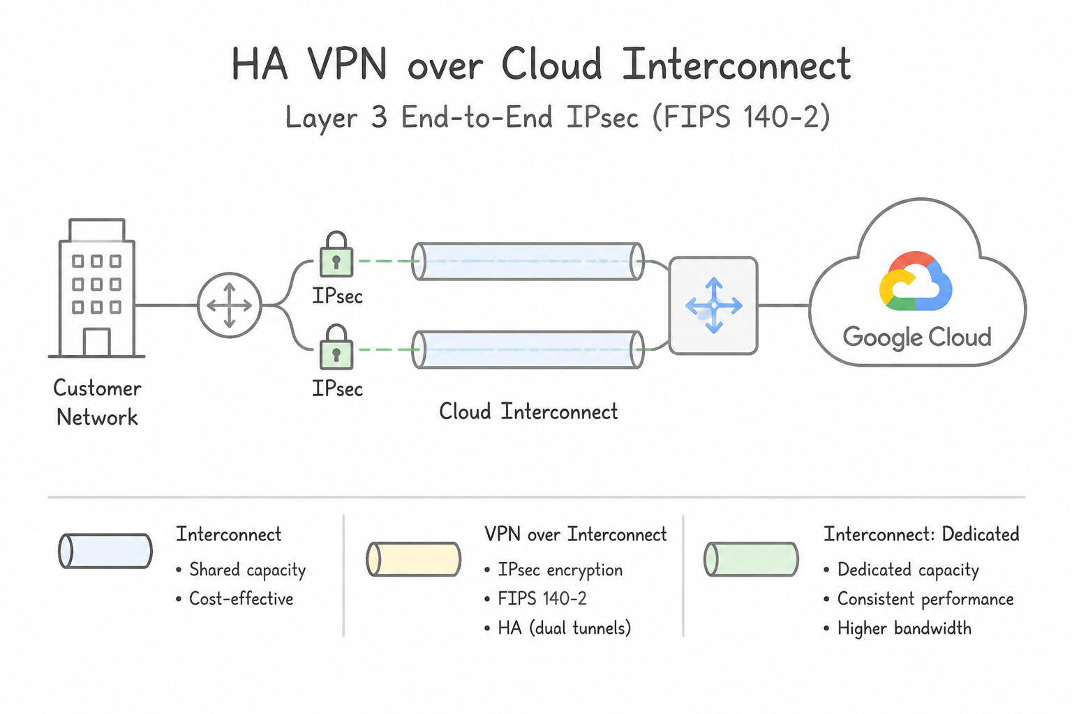
- Option 1: HA VPN over Cloud Interconnect (Layer 3 End-to-End IPsec, FIPS 140-2):
- Supported on both Dedicated Interconnect and Partner Interconnect.
- Deployment Hierarchy:
- Create Encrypted VLAN Attachments (
--encryption=IPSEC) and reserve a/29to/26internal regional IP address range for each attachment. - Deploy a special Encrypted Interconnect HA VPN Gateway (
--interconnect-attachmentbinding) whoseif0andif1interfaces bind directly to the two Encrypted VLAN Attachments (rather than public internet IPs). - Create a second Cloud Router (or separate BGP sessions on an HA VPN Cloud Router) to run the inner (overlay) encrypted IPsec BGP sessions on top of the outer (underlay) VLAN attachment BGP sessions.
- Bandwidth & MTU Considerations: Each HA VPN tunnel over Interconnect supports up to
250,000 packets per second(roughly 1.5–3 Gbps per tunnel depending on packet size; scale throughput by adding multiple HA VPN gateways/tunnels across the VLAN attachments). Set payload MTU to1440bytes to account for IPsec encapsulation overhead. - Option 2: MACsec for Cloud Interconnect (Layer 2 Link-Level
802.1AEEncryption): - Supported only on Dedicated Interconnect (10G and 100G links), not on Partner Interconnect (because the service provider switch sits in the middle at Layer 2).
- Encrypts traffic at line rate (10 Gbps / 100 Gbps) with near-zero throughput penalty between your colocation router and Google's edge router using pre-shared CAK/CKN keys.
Key Implementation Patterns
- Securing Highly Sensitive Data on Direct Interconnect: Use Deploy HA VPN gateways and configure VPN tunnels over the Interconnect attachments. HA VPN over Cloud Interconnect provides the required Layer 3 (IPsec) encryption over the existing physical link. (Avoid alternative: MACsec provides Layer 2 encryption, but the requirement specifies Layer 3 encryption.)
- Scaling Encrypted Throughput Beyond 3 Gbps: Use Create additional HA VPN tunnels and enable Equal-Cost Multi-Path (ECMP) routing. A single tunnel is limited to 3 Gbps; adding parallel tunnels with ECMP allows you to aggregate bandwidth to reach 10 Gbps. (Avoid alternative: MTU adjustments optimize packet size but do not increase the maximum throughput cap of the VPN encryption process.)
- Achieving 99.99% Availability with Encryption: Use Deploy two HA VPN gateways. Configure a total of four VPN tunnels, ensuring each tunnel is associated with a separate VLAN attachment. To match the 99.99% physical topology (4 paths), you need 4 tunnels provided by 2 HA VPN gateways.
Key Takeaways (4.1d)
- Dedicated Interconnect traffic is unencrypted by default.
- HA VPN over Cloud Interconnect provides Layer 3 IPsec encryption for private links.
- MACsec provides Layer 2 encryption for Dedicated Interconnect.
- Always match the encryption layer requirement (L2 vs. L3) to the specific technology (MACsec vs. IPsec).
Consideration 4.1e: Implementing SLA architectures
- Edge Availability Domains (
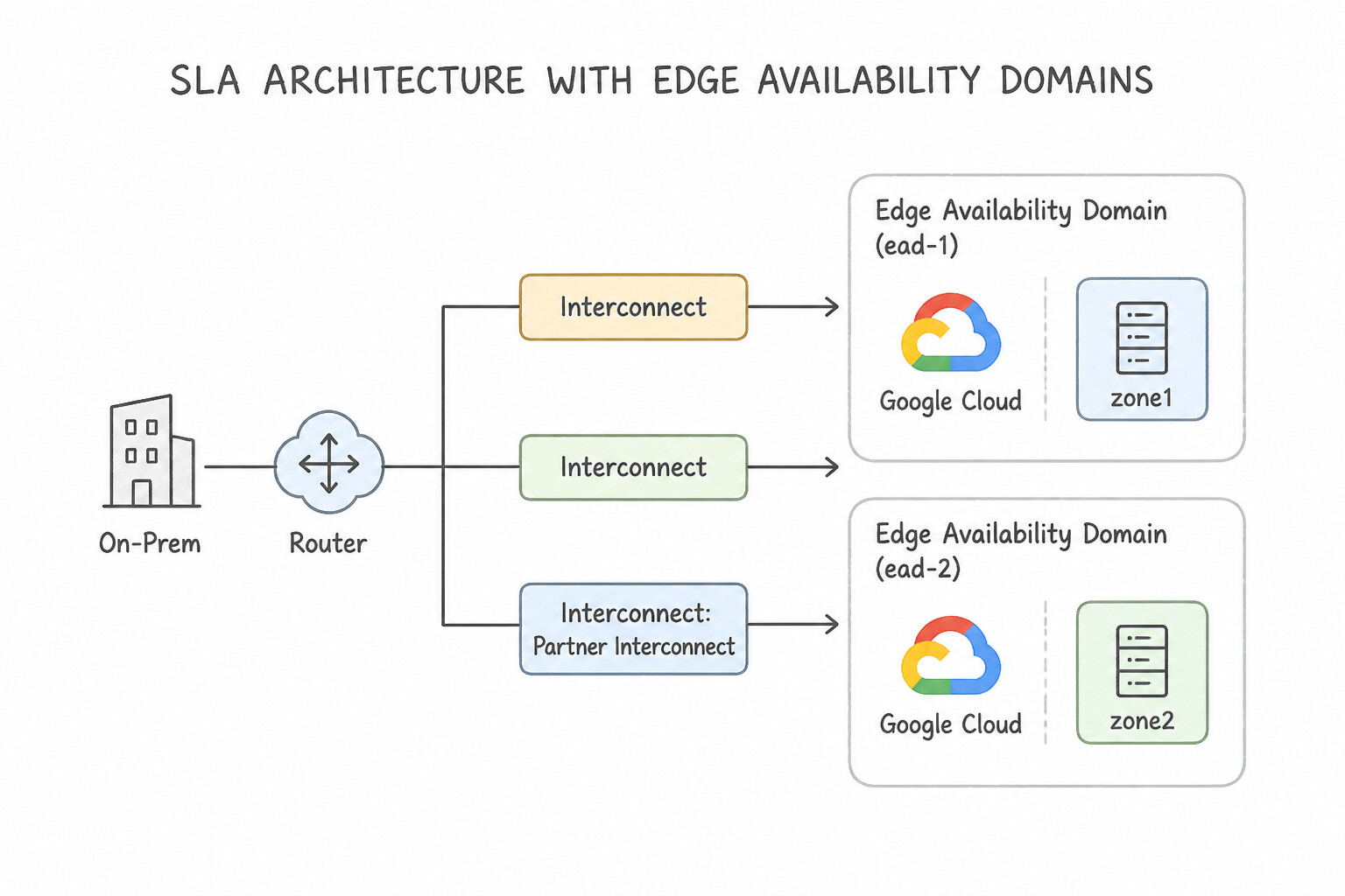
ead-1/zone1andead-2/zone2): - Every Google Cloud Interconnect metro facility is split into two isolated maintenance domains called Edge Availability Domains (
zone1andzone2). Google never performs planned maintenance onzone1andzone2in the same metro simultaneously. - architectures Rule: When pairing two circuits in the same metro, one must be in
zone1and the other must be inzone2. - 99.9% SLA Topology ("Two of Everything in One Metro"):
- Minimum Requirements:
- 2 Interconnect Connections (or 2 Partner VLAN attachments) in 1 Metro, placed in 2 distinct Edge Availability Domains (
zone1andzone2). - 2 VLAN Attachments (one on each connection) connected to 1 (or 2) Cloud Router(s) in 1 Google Cloud Region.
- Useful for non-critical workloads or when all workloads reside in a single region and can tolerate a metro-wide facility failure.
- 99.99% SLA Topology ("Four of Everything across Two Metros & Two GCP Regions"):
- Minimum Requirements:
- 4 Interconnect Connections (or 4 Partner VLAN attachments) split across 2 distinct Metropolitan Areas (Metros) (2 connections in Metro A [
zone1,zone2] + 2 connections in Metro B [zone1,zone2]). - 4 VLAN Attachments terminating on at least 2 Cloud Routers located in 2 different Google Cloud Regions (e.g.,
us-east1andus-central1) within the same VPC. - VPC Dynamic Routing Mode MUST be set to
GLOBAL(--bgp-routing-mode=GLOBAL) so that if both circuits in Region A (us-east1) fail, traffic tous-east1VMs can seamlessly route through Region B (us-central1) over Google's backbone!
Key Implementation Patterns
- Designing for 99.99% Availability with Dedicated Interconnect: Use Provision four dedicated connections across two different metropolitan areas. In each area, ensure two connections use different edge availability domains. For 99.99% SLA, you must use four connections distributed across two different metropolitan areas.
- Achieving 99.9% SLA with Minimum Hardware: Use Provision two connections in the same metropolitan area. Place the connections in two different edge availability domains. The 99.9% SLA requires two connections in a single metro area, split across two different edge availability domains.
- Partner Interconnect and 99.99% SLA Configuration: Use Request four VLAN attachments across two metropolitan areas. Configure two VLAN attachments in each metropolitan area. For a 99.99% SLA, you must use four VLAN attachments spread across two metropolitan areas (two per metro).
Key Takeaways (4.1e)
- 99.9% SLA requires 2 connections in 1 metropolitan area (different zones).
- 99.99% SLA requires 4 connections across 2 metropolitan areas (2 connections per metro).
- Redundancy across metros protects against regional disasters.
- Redundancy within a metro protects against hardware maintenance or failure.
Quick Decision Cheat Sheet (Subsection 4.1)
If the Scenario Requires... | Choose This Google Cloud Pattern | Avoid This Common Mistake |
|---|---|---|
"Dedicated Interconnect 99.99% SLA" | 4 Connections across 2 Metros ( zone1 & zone2 in each), 4 VLAN Attachments across 2 GCP Regions, Global Dynamic Routing | 2 Connections in 1 Metro (only achieves 99.9% SLA) or 4 Connections in 1 Metro |
"Dedicated Interconnect 99.9% SLA" | 2 Connections in 1 Metro ( zone1 & zone2), 2 VLAN Attachments in 1 GCP Region | 1 Connection with 2 x 10G links in an LACP bundle (single Edge Availability Domain = no SLA) |
"Need < 10 Gbps (e.g., 500 Mbps or 2 Gbps) private circuit OR cannot reach a Google colocation facility" | Partner Interconnect (supports 50 Mbps to 50 Gbps per VLAN attachment) | Dedicated Interconnect (minimum 10 Gbps physical port inside a colocation facility) |
"Letter of Authorization and Connecting Facility Assignment (LOA-CFA)" | Dedicated Interconnect (or Cross-Cloud Interconnect) physical cross-connect ordering artifact | Partner Interconnect (uses a Pairing Key instead of an LOA-CFA) |
"Layer 2 vs. Layer 3 Partner Interconnect BGP ASN" | Layer 2 = Customer's on-prem ASN on Cloud Router; Layer 3 = Service Provider's ASN on Cloud Router | Using Customer's ASN on a Layer 3 Partner Interconnect |
"Single 10 Gbps Dedicated Interconnect link fails to come up after fiber cross-connect" | Enable 802.3ad LACP on the on-premises router port (mandatory on Dedicated Interconnect even for a 1-link bundle) | Disabling 802.1Q VLAN tagging or configuring static routes without BGP |
Further Reading (Subsection 4.1)
- Dedicated Interconnect provisioning overview — Review the 'Order an Interconnect connection' section, specifically the steps following the order submission where the LOA-CFA is discussed.
- Establishing 99.99% availability for Dedicated Interconnect — This section details the exact topology required: four connections across two metros to achieve 99.99% availability.
- Dedicated Interconnect Overview — Refer to the 'Requirements' or 'Configuration' section where it specifies that LACP must be enabled and configured in Active mode on the on-premises router.
- Partner Interconnect provisioning overview — Review the 'Provisioning' section which details the workflow involving the pairing key and the service provider.
- Create VLAN attachments — Provides step-by-step instructions on creating the attachment and locating the pairing key.
- Partner Interconnect Overview - SLA Requirements — This section explicitly details the topology requirements for 99.9% and 99.99% availability, stating 'To achieve 99.99% availability for Partner Interconnect, you must create four VLAN attachments... two in one metro... and two in another metro.'
Subsection 4.2: Configuring a site-to-site IPSec VPN
The Big Picture
When organizations rely on legacy Classic VPN (or misconfigure HA VPN), they routinely suffer unexpected tunnel flaps, sub-99.99% availability gaps, and silent packet blackholes caused by mismatched IPsec Traffic Selectors or MTU fragmentation. Classic VPN exposes only a single external IP interface without physical gateway redundancy (99.9% SLA max), requires static route maintenance when using policy-based or static route-based tunnels, and breaks completely whenever subnet layouts change on either side of a policy-based IKEv1 tunnel.
HA VPN eliminates these failure modes by provisioning a regional dual-interface gateway (interface 0 and interface 1) backed by two completely isolated Google Cloud physical/network pools and dynamically exchanging routes via Cloud Router eBGP over 169.254.0.0/16 link-local /30 tunnel interfaces. However, to actually achieve the 99.99% SLA with HA VPN, you must wire tunnels according to strict interface redundancy rules depending on whether your External Peer VPN Gateway has 2 interfaces (2 tunnels: if0->peer0, if1->peer1) or 4 interfaces like AWS Site-to-Site VPN (4 tunnels required), and if your peer device only has 1 public IP, you cannot achieve the 99.99% SLA even with two tunnels!
Consideration 4.2a: Configuring HA VPN to on-prem
- Dual-Interface Architecture (
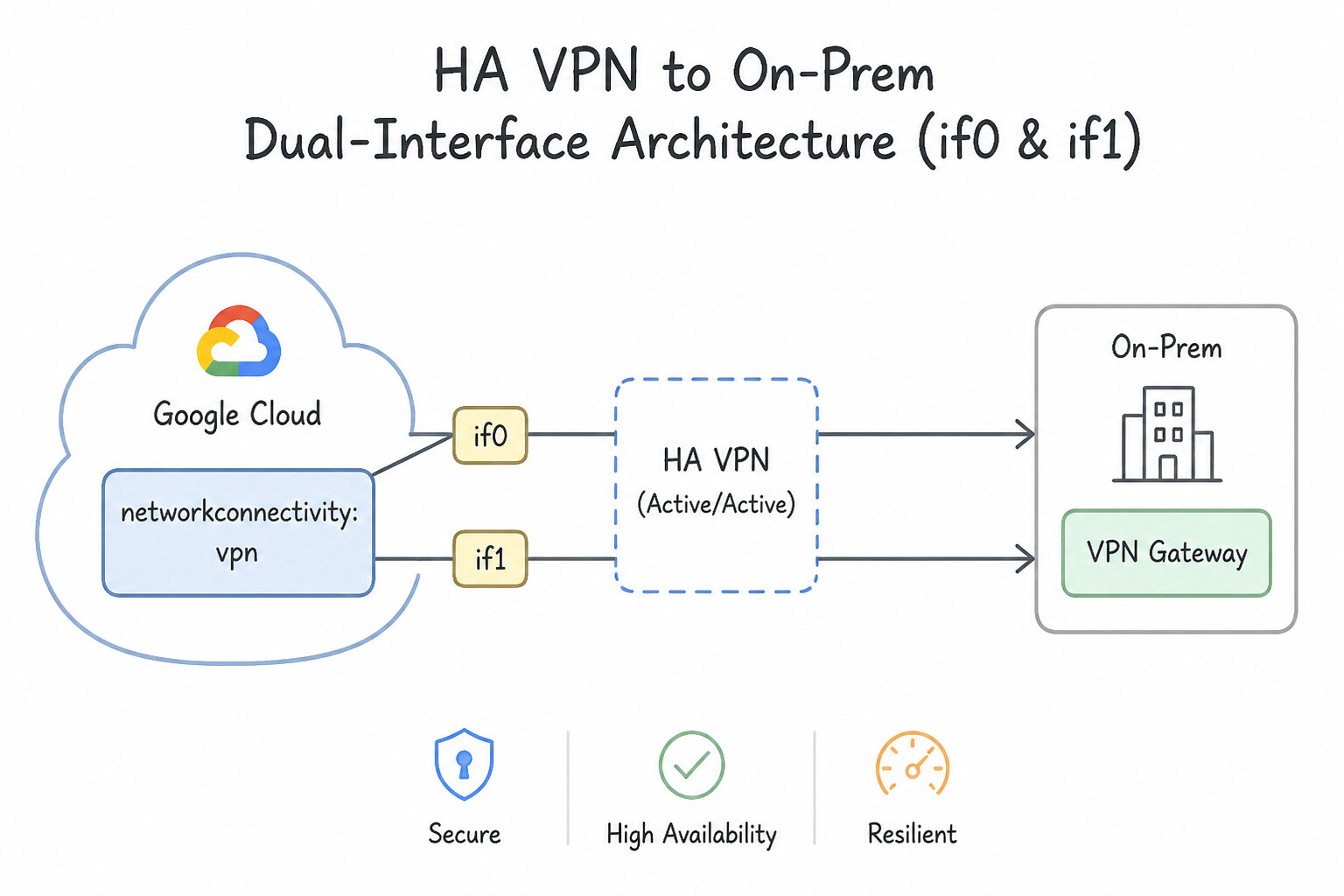
if0andif1): - When you create an HA VPN Gateway (
compute vpn-gateways create), Google Cloud automatically allocates two distinct regional external IPv4 addresses—one forinterface 0and one forinterface 1—drawn from two completely separate network prefixes and physical PoP clusters to prevent any single point of failure. - Supports IPv4 and dual-stack (IPv4 + IPv6) traffic inside the tunnels, using IKEv2 (recommended) or IKEv1 with Cloud Router dynamic eBGP on
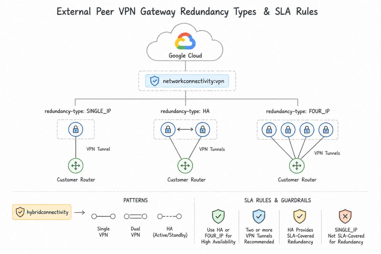
169.254.x.x/30link-local interface addresses. - External Peer VPN Gateway Redundancy Types (
--redundancy-type) & SLA Rules: TWO_IPS_REDUNDANCY: The on-premises side has two redundant VPN gateway devices (or active-active dual ISP links) with 2 public IPs. You create 2 VPN tunnels (if0 -> peer_if0andif1 -> peer_if1). Achieves 99.99% SLA.FOUR_IPS_REDUNDANCY: Designed specifically for AWS Site-to-Site VPN (where each AWS VPN Connection provides 2 public tunnel endpoints, so 2 AWS VPN connections = 4 public IPs). You create 4 VPN tunnels (if0to AWS Connection 1's two IPs, andif1to AWS Connection 2's two IPs). Achieves 99.99% SLA.SINGLE_IP_INTERNALLY_REDUNDANT: The on-premises device exposes only 1 public IP address. Even though you must connect bothif0andif1(2 tunnels total) to that single peer IP, Google Cloud only guarantees a 99.9% SLA (not 99.99%) because the single peer IP represents an external single point of failure.- Throughput, MTU, and UDP Encapsulation:
- Each individual HA VPN tunnel supports up to
250,000 packets per second(aggregate ingress + egress) or roughly 1.5–3 Gbps depending on packet size and cipher (AES-GCMrecommended). To scale bandwidth beyond 3 Gbps, deploy multiple HA VPN tunnels/gateways using ECMP (Equal-Cost Multi-Path) across identical BGP MEDs. - MTU Best Practice: Because IPsec headers add ~54–74 bytes of encapsulation overhead, configure the VPN tunnel / gateway payload MTU to
1460bytes (or1440bytes) and enable TCP MSS clamping (1360–1400bytes) on the on-premises firewall to prevent IP fragmentation drops. - Firewall Ports Required on On-Premises: Allow UDP port
500(IKE), UDP port4500(NAT-T encapsulation), and IP Protocol50(ESP).
Key Implementation Patterns
- Achieving 99.99% Availability with HA VPN: Use Configure four VPN tunnels. Connect the first interface of the HA VPN gateway to both on-premises IP addresses. Connect the second interface to both on-premises IP addresses. For a 99.99% SLA with two on-premises public IPs, you must configure a full mesh of four tunnels connecting both cloud interfaces to both peer IPs.
- IKE Version Mismatch Troubleshooting: Use Update the on-premises router configuration to use IKEv2. HA VPN strictly requires IKEv2, whereas Classic VPN supported IKEv1; the on-premises router must be updated to match. (Avoid alternative: Restarting the gateway does not change the supported protocol versions or fix configuration mismatches.)
Key Takeaways (4.2a)
- Cloud HA VPN gateways have two interfaces to provide redundancy.
- A 99.99% SLA requires redundancy on both the Google Cloud side and the peer side.
- When connecting to a peer with two public IP addresses, you must configure four tunnels (Interface 0 to Peer A, Interface 0 to Peer B, Interface 1 to Peer A, Interface 1 to Peer B).
- Failing to configure the full mesh of tunnels may result in a lower availability SLA (e.g., 99.9%).
Consideration 4.2b: Configuring HA VPN between VPCs
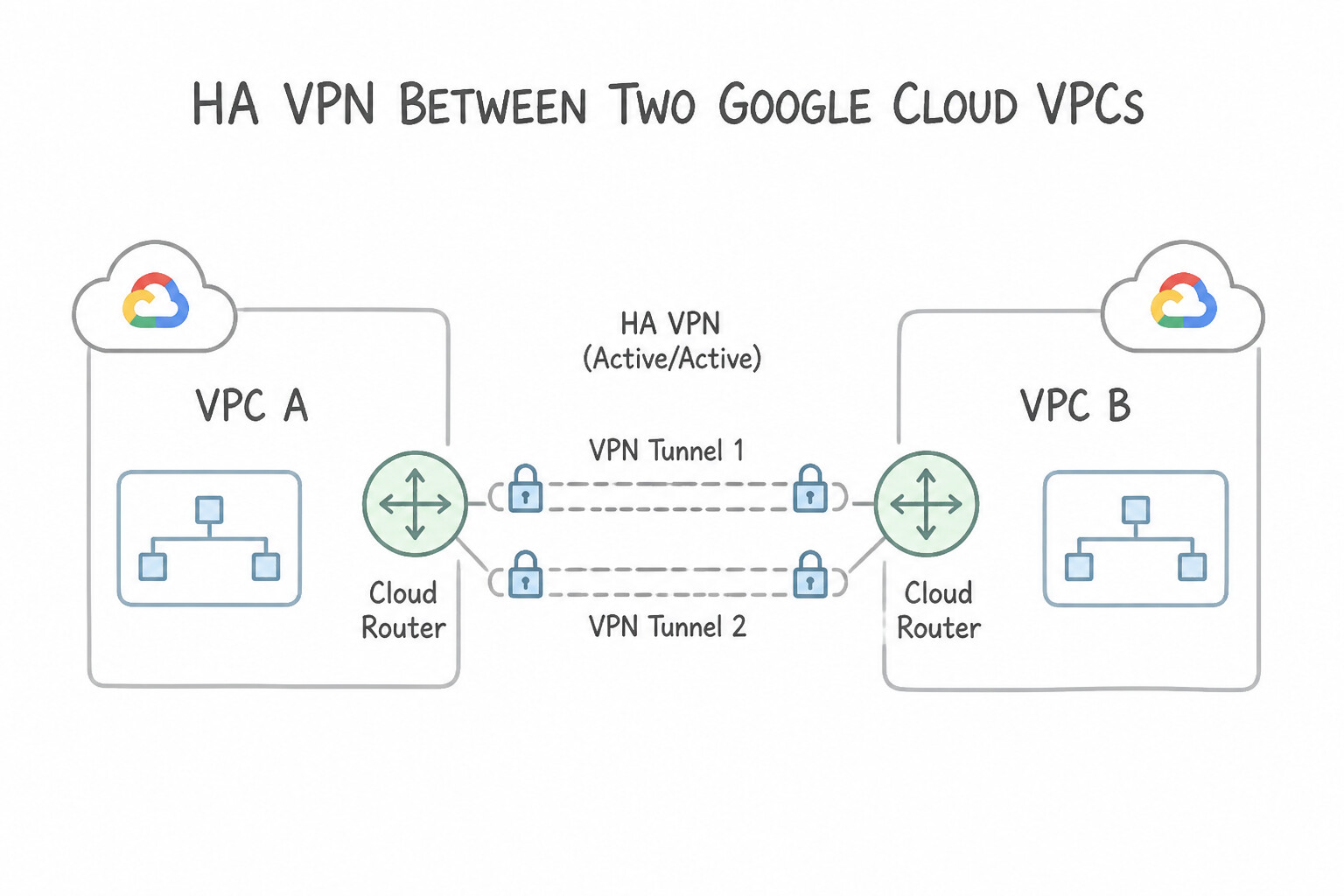
- When to Use HA VPN Between Two Google Cloud VPCs:
- While VPC Network Peering and Network Connectivity Center (NCC) provide direct Andromeda SDN connectivity without tunnel bandwidth bottlenecks, architects use VPC-to-VPC HA VPN when:
- Overlapping Subnet CIDRs exist elsewhere and only specific non-overlapping subnets/custom routes (or NATed CIDRs) should be exchanged via Cloud Router BGP filters.
- Transitive Routing is Required across multiple VPCs (since VPC Network Peering is strictly non-transitive, whereas BGP routes learned over HA VPN can be re-advertised via custom route advertisements or combined with VPC Peering / NCC).
- Connecting across different Google Cloud Organizations where security policy mandates Cloud Router BGP route filtering and IPsec tunnel boundaries rather than VPC Peering.
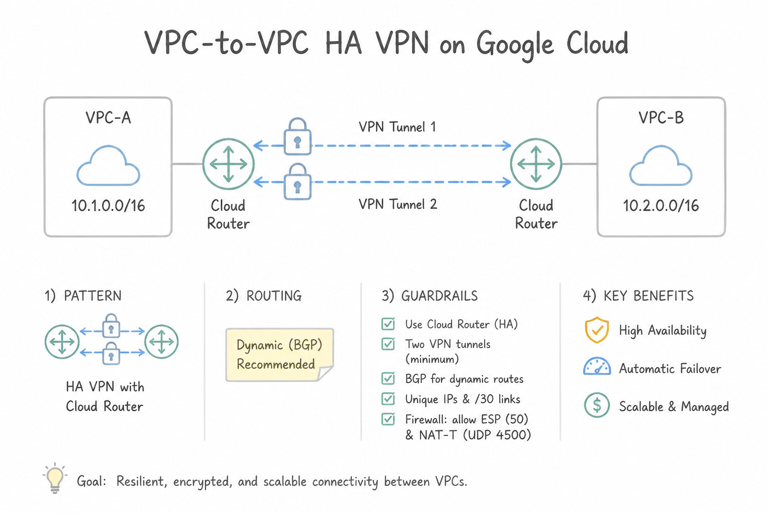
- Configuring VPC-to-VPC HA VPN:
- In VPC A, create
ha-vpn-gw-aandcloud-router-a(e.g., ASN65001). In VPC B, createha-vpn-gw-bandcloud-router-b(e.g., ASN65002— ASNs MUST be different because Cloud Router uses eBGP!). - When creating the VPN tunnels in VPC A, specify
--peer-gcp-gateway=ha-vpn-gw-b(rather than--peer-external-gateway). - Wire 2 tunnels (
if0 -> if0andif1 -> if1) between the two HA VPN gateways to immediately satisfy the 99.99% SLA.
Key Implementation Patterns
- Achieving 99.99% SLA in VPC-to-VPC Topology: Use Create two VPN tunnels on each gateway, connecting interface 0 to interface 0 and interface 1 to interface 1. You must connect both pairs of interfaces (0-to-0 and 1-to-1) to achieve the 99.99% SLA. (Avoid alternative: VPC Peering does not use the HA VPN gateways and operates differently from the required VPN SLA configuration.)
- BGP ASN Configuration for Inter-VPC VPN: Use Configure the Cloud Routers to use different Autonomous System Numbers (ASNs). BGP sessions between two VPCs require unique ASNs on each Cloud Router to establish correctly. (Avoid alternative: Using the same ASN on both sides triggers BGP loop detection and prevents successful peering.)
- Configuring Active/Passive Routing via MED: Use Configure the Cloud Router to advertise a lower Multi-Exit Discriminator (MED) value for the BGP sessions on the primary tunnels. Lower MED values are preferred in BGP. Advertising a lower MED on the primary tunnels ensures they are chosen as the active path.
Key Takeaways (4.2b)
- HA VPN gateways have two interfaces (0 and 1) to support redundancy.
- A 99.99% SLA requires configuring tunnels for both interfaces.
- For VPC-to-VPC HA VPN, connect Interface 0 to Interface 0 and Interface 1 to Interface 1.
- Classic VPN is legacy and should be avoided for new high-availability requirements.
Consideration 4.2c: Configuring Classic VPN
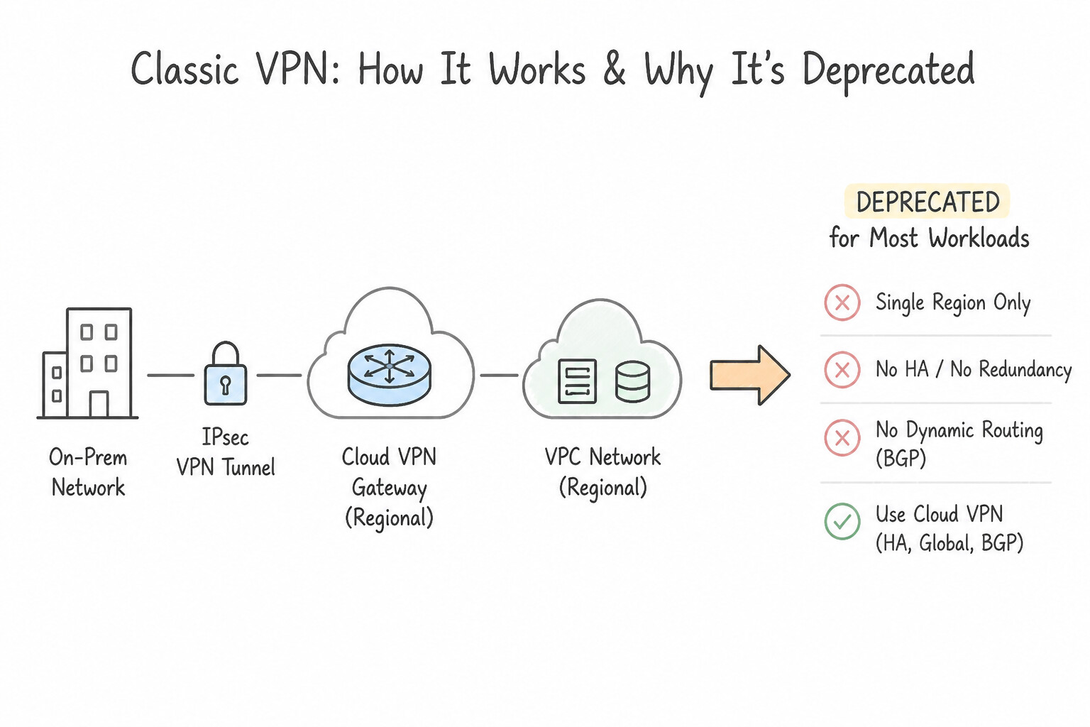
- Why Classic VPN is Deprecated for Most Workloads:
- A Classic VPN (
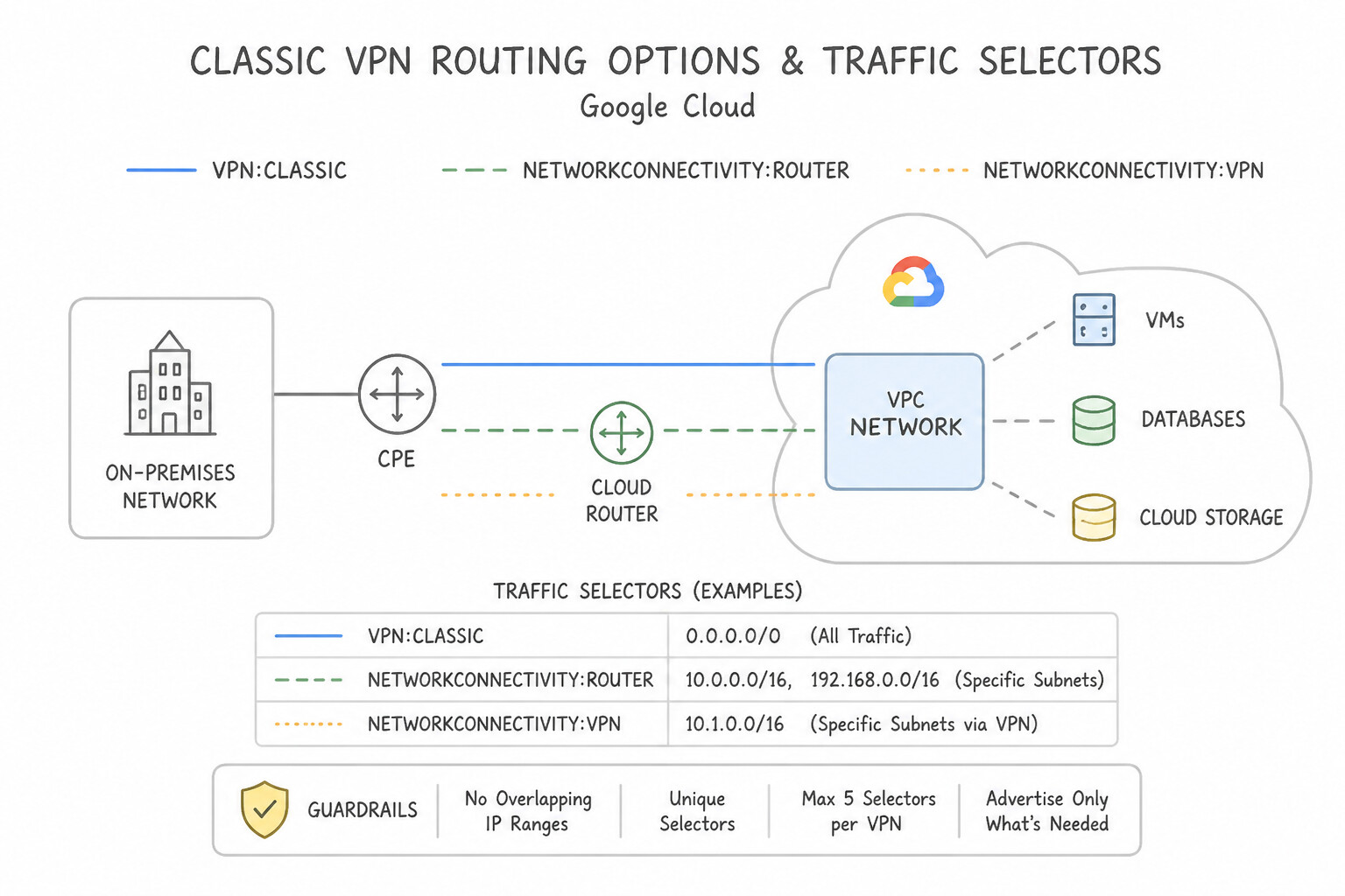
compute target-vpn-gateways) has only one external IP address, offers only a 99.9% SLA, does not support IPv6, and requires separate forwarding rules (ESP,UDP 500,UDP 4500). - Classic VPN Routing Options & Traffic Selectors:
- Dynamic Routing (BGP): Uses Cloud Router just like HA VPN (traffic selectors default to
0.0.0.0/0on both sides). - Route-Based VPN: Uses static routes where the tunnel's local and remote traffic selectors are both set to
0.0.0.0/0(--local-traffic-selector=0.0.0.0/0 --remote-traffic-selector=0.0.0.0/0), and you manually create VPC static routes pointing to the tunnel. - Policy-Based VPN: Explicitly lists subnet CIDRs in
--local-traffic-selector(GCP subnets) and--remote-traffic-selector(on-premises subnets). - Policy-Based VPN Traps (Production Integration Pattern):
- If a new subnet is added to the Google Cloud VPC or on-premises network, a policy-based Classic VPN tunnel cannot simply be updated in-place—you must delete and recreate the VPN tunnel with the updated traffic selectors, causing downtime!
- Many on-premises IKEv1 firewalls create a separate IPsec Security Association (Child SA) per subnet pair if multiple CIDRs are listed in a traffic selector; Google Cloud consolidates them into a single SA, causing tunnel drop unless CIDRs are summarized or migrated to Route-Based / Dynamic BGP.
- Seamless Zero-Downtime Migration from Classic VPN to HA VPN:
- Deploy the HA VPN Gateway, Cloud Router, and 2 redundant HA VPN tunnels alongside the existing active Classic VPN tunnel in the same VPC.
- Establish the eBGP sessions over the new HA VPN tunnels and verify that identical prefixes are learned on both the Google Cloud and on-premises sides.
- Adjust BGP route priorities (MED / Local Preference) so both Google Cloud and on-premises prefer the HA VPN tunnels over the legacy Classic VPN static/BGP routes.
- Verify zero traffic on the Classic VPN monitoring metrics, then decommission the Classic VPN tunnels and static routes.
Key Implementation Patterns
- Legacy Device Static Routing Configuration: Use Create a route-based VPN tunnel and configure static routes for the on-premises IP address ranges. Without BGP support, you must manually configure static routes pointing to the route-based VPN tunnel. (Avoid alternative: Cloud Router requires BGP, which the on-premises device does not support.)
- Policy-Based VPN Traffic Selectors: Use Set the Local traffic selector to the VPC subnet ranges and the Remote traffic selector to the partner's on-premises ranges. Policy-based VPNs require explicit traffic selectors; Local must match the VPC ranges, and Remote must match the on-premises ranges.
- Manual Forwarding Rules for Classic VPN: Use Create three forwarding rules pointing to the gateway: one for UDP port 500, one for UDP port 4500, and one for ESP (IP protocol 50). Classic VPN requires three forwarding rules: UDP 500 for IKE, UDP 4500 for NAT-T, and IP protocol 50 (ESP) for encrypted data.
Key Takeaways (4.2c)
- HA VPN mandates the use of BGP; it does not support static routing.
- Classic VPN supports both dynamic (BGP) and static routing.
- If an on-premises peer device does not support BGP, you must use Classic VPN with static routes (route-based) or policy-based routing.
- Route-based VPNs with static routes offer more flexibility than policy-based VPNs.
Quick Decision Cheat Sheet (Subsection 4.2)
If the Scenario Requires... | Choose This Google Cloud Pattern | Avoid This Common Mistake |
|---|---|---|
"HA VPN 99.99% SLA with TWO_IPS_REDUNDANCY" | 2 Tunnels: interface 0 -> Peer IP 0 AND interface 1 -> Peer IP 1 | 2 Tunnels both originating from interface 0 |
"HA VPN 99.99% SLA with FOUR_IPS_REDUNDANCY (AWS)" | 4 Tunnels: if0 -> Peer IPs 0 & 1; if1 -> Peer IPs 2 & 3 | Only 2 tunnels connected to 2 of the 4 peer IPs |
"On-premises VPN device does NOT support BGP at all" | Classic VPN (Route-Based 0.0.0.0/0 preferred over Policy-Based) | HA VPN (HA VPN strictly requires dynamic BGP via Cloud Router) |
"Large packets or HTTPS handshakes hang over a newly established HA VPN tunnel" | Lower VPN tunnel MTU to 1460 / 1440 bytes and clamp TCP MSS to 1360 bytes | Switching from IKEv2 to IKEv1 or changing the BGP hold timer |
"Migrate from Classic VPN to HA VPN without packet loss or downtime" | Build HA VPN in parallel, establish BGP, prefer HA VPN routes via lower MED / higher LocalPref, then delete Classic VPN | Deleting the Classic VPN tunnel first to reuse the same static routes |
"BGP link-local peering IP address range on HA VPN tunnels" | 169.254.0.0/16 (/30 subnet per tunnel) excluding reserved 169.254.169.254 | Using RFC 1918 VPC subnet IPs as the inner BGP tunnel interface IPs |
Further Reading (Subsection 4.2)
- Cloud VPN topologies — Refer to the section '99.99% availability' and specifically 'Peer VPN gateway with two interfaces' which details the requirement for four tunnels.
- Cloud VPN Overview — See the section on 'Specifications' or 'IKE support' which specifies that HA VPN only supports IKEv2.
- HA VPN topologies - Google Cloud — Refer to the section 'HA VPN between Google Cloud networks' to see the topology diagram and the requirement for two tunnels to achieve 99.99% SLA.
- Create an HA VPN gateway to a peer VPN gateway — See the section on configuring BGP sessions where it specifies that you must configure a unique ASN for each Cloud Router.
- Active/passive routing in HA VPN — This section explains how to configure Cloud Router to advertise distinct MED values to achieve an active/passive topology.
- Networks and tunnel routing — Details the routing options for Classic VPN, including static routing and policy-based routing.
Subsection 4.3: Configuring Cloud Router
The Big Picture
A critical misconception among network engineers new to Google Cloud is assuming that Cloud Router is a physical or virtual data-plane router through which packets flow. In reality, Cloud Router is purely a control-plane speaker: it runs in the control plane to exchange BGP prefixes with your on-premises or multicloud routers and programs the learned routes directly into the VPC's Andromeda SDN forwarding table. If a Cloud Router software process restarts during maintenance, zero packets are dropped in the data plane! However, because engineers misunderstand how Google Cloud translates BGP attributes (MED, AS-Path, and inter-region cost penalties) into VPC route priorities, they frequently cause asymmetric routing (where traffic enters Google Cloud in us-east1 via Interconnect but exits back to on-premises via us-west1 over a backup VPN tunnel, getting dropped by stateful on-premises firewalls).
Furthermore, relying on default BGP timers (60s keepalive / 180s hold time, or 20s/60s on Cloud Router) means that when a Layer 2 Partner Interconnect or physical transit switch fails without dropping link light on the local router interface, traffic blackholes for up to 60 seconds before BGP reconverges. Enabling Bidirectional Forwarding Detection (BFD) drops failure detection down to sub-second intervals (300ms x 3 = ~900ms), while Custom-Advertised Routes (199.36.153.8/30 for Private Google Access, 35.199.192.0/19 for Cloud DNS) and Custom-Learned Routes (BGP-tracked static routes) give you deterministic control over hybrid reachability.
Consideration 4.3a: Configuring BGP attributes
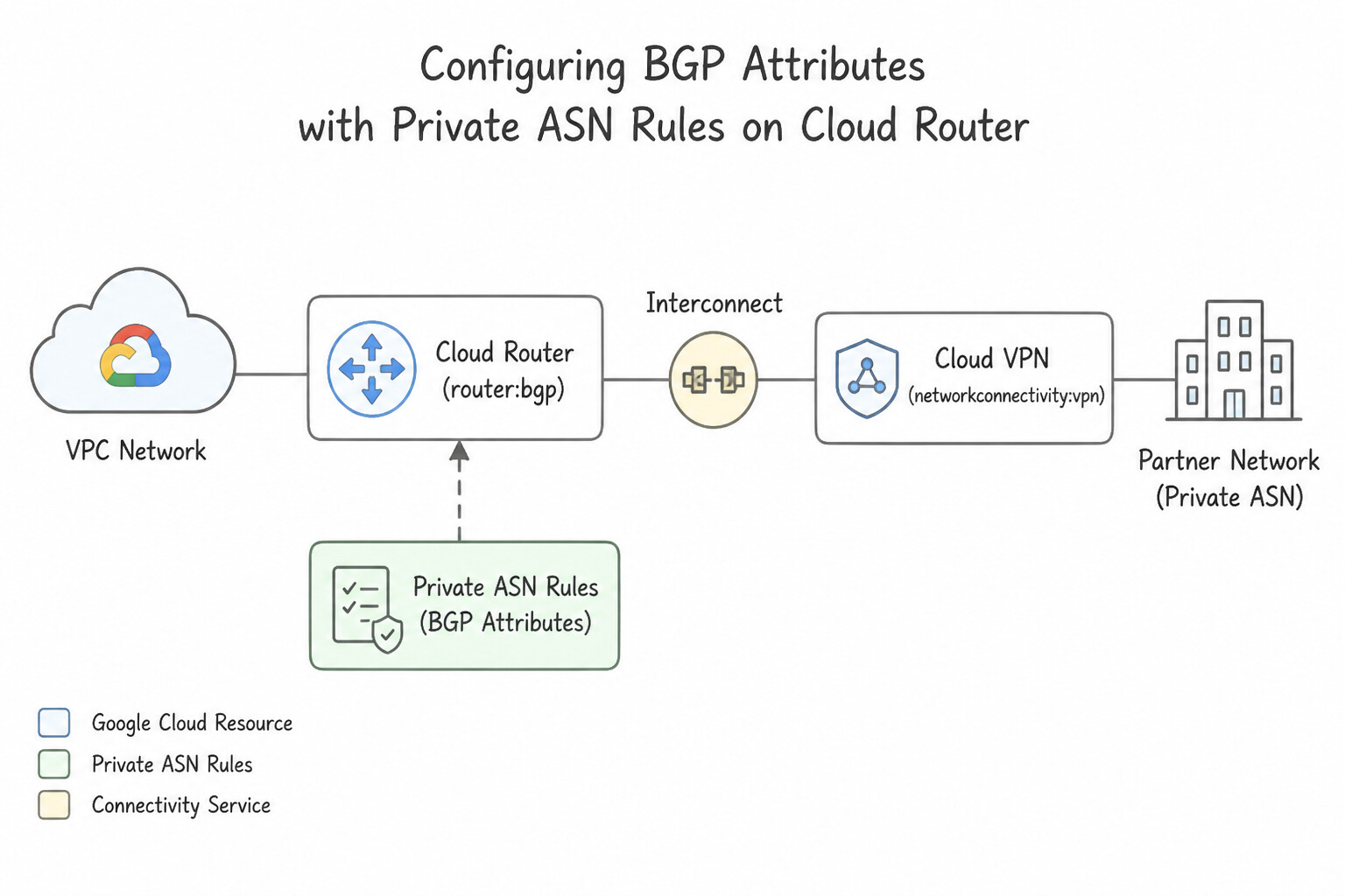
- Private ASN Rules on Cloud Router:
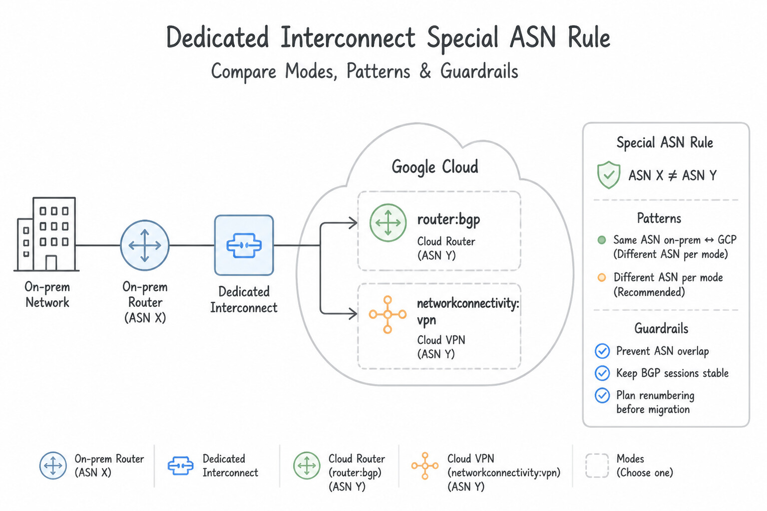
- Cloud Router strictly uses eBGP (external BGP); the Cloud Router ASN and the peer router ASN must be different.
- Supports both 16-bit private ASNs (
64512–65534) and 32-bit private ASNs (4200000000–4294967294). - Dedicated Interconnect Special ASN Rule: For Dedicated Interconnect, every Cloud Router in the same region using Dedicated Interconnect must use the Google-mandated local ASN
16550! For HA VPN and Partner Interconnect, you choose any private ASN not already in use by the peer. - How Cloud Router Uses MED (Base & Regional Route Priority):
- On a Cloud Router BGP session, the Advertised Route Priority (
--advertised-route-priority, default100, range0–65535) is advertised to your on-premises router as the BGP Multi-Exit Discriminator (MED) attribute (lower value is preferred!). - When Global Dynamic Routing is enabled on the VPC, a Cloud Router in
us-east1advertises: us-east1(local) subnets with the Base Priority (e.g.,MED = 100).us-west1(remote) subnets with Base Priority + Regional Cost Penalty (e.g.,100 + 208 = 308, where the regional penalty ranges from201to9999based on physical inter-region latency/distance).- This automatic MED adjustment ensures on-premises routers naturally send traffic for
us-east1into theus-east1tunnel and traffic forus-west1into theus-west1tunnel! - When MED Fails on On-Premises Routers -> Use AS-Path Prepending:
- Major common pitfalls: According to RFC 4271, BGP routers only compare
MEDbetween routes learned from the SAME neighbor ASN (unlessbgp always-compare-medis explicitly configured on the on-premises router). - If your primary path is a Dedicated Interconnect (ASN
16550) and your backup path is an HA VPN (ASN65001)—or two different Partner Interconnect providers with different ASNs—your on-premises router will ignore MED when choosing between them! - Fix: Either enable
bgp always-compare-medon the on-premises router, OR configure AS-Path Prepending on the backup Cloud Router / on-premises session so the backup path has a longerAS_PATH(sinceAS_PATHlength is evaluated beforeMEDand across all ASNs).
Key Implementation Patterns
- Configuring Active/Passive Failover with Route Priority: Use Update the Cloud Router BGP session for the first tunnel with a lower Advertised Route Priority value than the second tunnel. Advertised Route Priority sets the MED value sent to the peer; a lower value tells the peer to prefer this path for sending traffic to Google Cloud.
- Enabling ECMP over Cloud Interconnect: Use Configure both BGP sessions with the same advertised route priority. ECMP requires identical advertised route priorities (MED values) on all BGP sessions to treat links as equal. (Avoid alternative: BFD is used for fast failure detection, not for configuring traffic load balancing strategies.)
- Restricting Subnet Advertisements for Security: Use Edit the Cloud Router BGP session. Set the route advertisement mode to custom. Add the IP address ranges for the Prod and Dev subnets. Switching to custom route advertisement allows you to explicitly list which subnets to advertise, excluding any others.
Key Takeaways (4.3a)
- Advertised Route Priority controls ingress traffic (On-prem to GCP) by setting the MED.
- Lower MED values are preferred by BGP peers.
- Base Priority controls egress traffic (GCP to On-prem).
- Active/Passive failover is achieved by assigning different priorities to the primary and secondary paths.
Consideration 4.3b: Configuring BFD
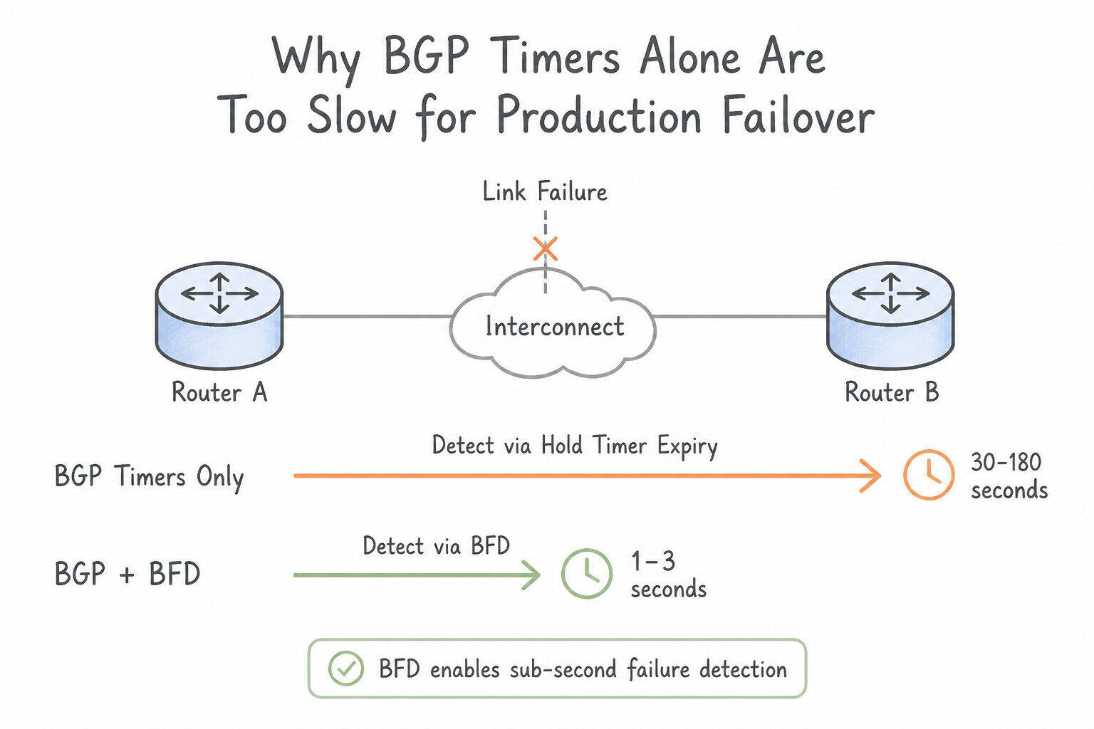
- Why BGP Timers Alone Are Too Slow for Production Failover:
- Cloud Router's default BGP keepalive timer is
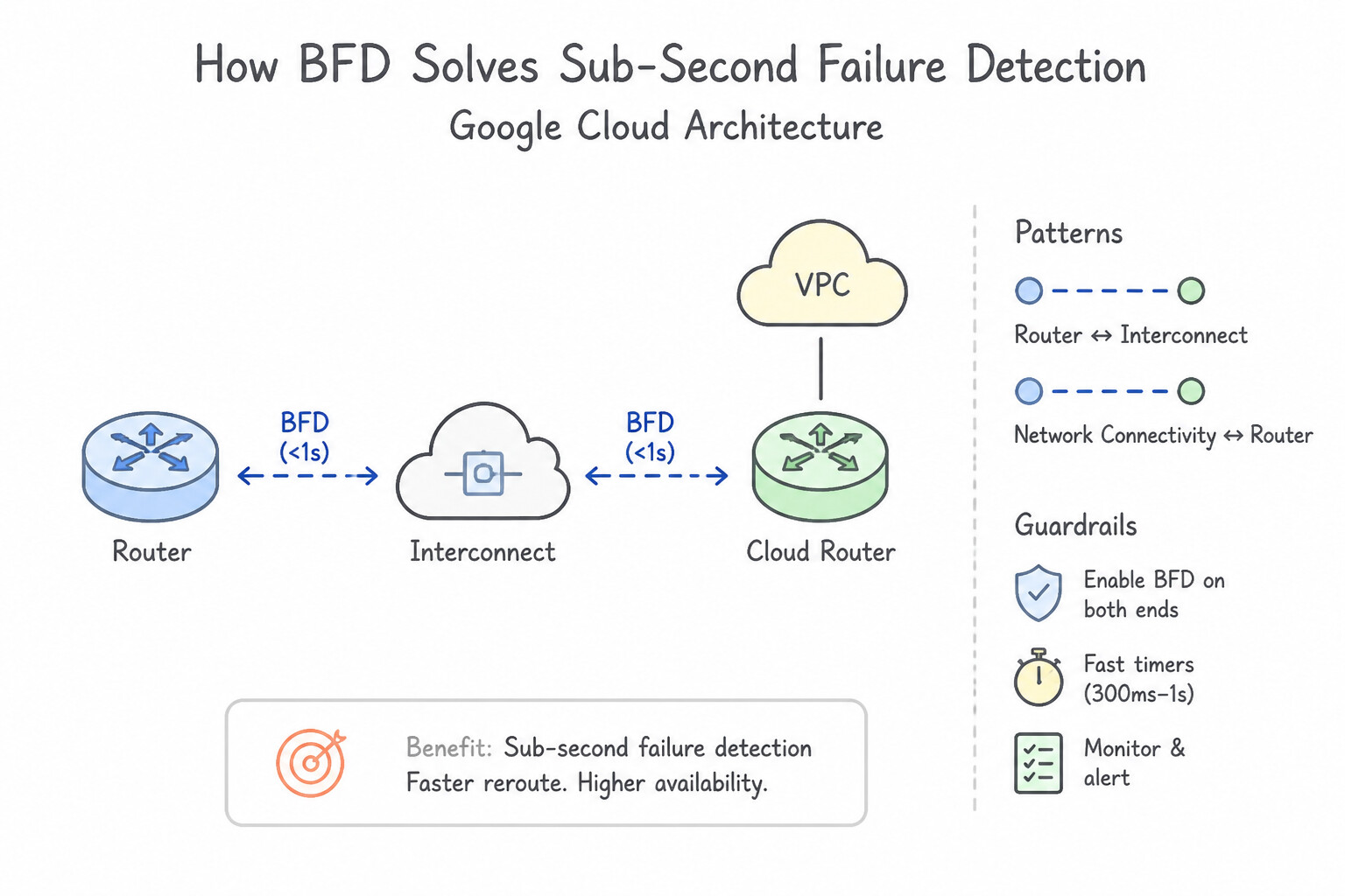
20seconds and hold timer is60seconds. If a Layer 2 intermediate switch or dark fiber path fails without bringing down the local physical interface on the router, BGP waits a full 60 seconds before declaring the peer dead and withdrawing routes. - How BFD Solves Sub-Second Failure Detection:
- Bidirectional Forwarding Detection (BFD) (
RFC 5880) is a lightweight, low-overhead hello protocol that runs over the data-plane forwarding path on Dedicated Interconnect VLAN attachments, Partner Interconnect VLAN attachments, and HA VPN tunnels. - Cloud Router supports Single-Hop BFD (
--bfd-session-initialization-mode=ACTIVEorPASSIVE). - Timers & Multiplier:
- Default minimum transmit/receive interval is
1000 ms(1 second) (configurable down to300 mson Interconnect) with a detection multiplier of3(--bfd-multiplier=3), enabling failure detection and BGP failover in 1 to 3 seconds instead of 60 seconds. - Troubleshooting Trap: For BFD to come up in active mode, at least one side must be
ACTIVE(not bothPASSIVE), and both sides must agree on single-hop encapsulation over the169.254.x.x/30link-local peering IPs.
Key Implementation Patterns
- Minimizing Failover Time for Low-Latency Apps: Use Enable Bidirectional Forwarding Detection (BFD) on the BGP session. BFD is the standard feature for achieving sub-second link failure detection on Cloud Router. (Avoid alternative: Lowering BGP timers to 1 second causes instability and high CPU usage; it is not the correct method for sub-second detection.)
- BFD Interaction with BGP Graceful Restart: Use Disable BGP Graceful Restart on the Cloud Router BGP session. Graceful Restart keeps routes active during failures; disable it to allow BFD to immediately withdraw routes upon failure detection. (Avoid alternative: Increasing the transmit interval slows down failure detection, which contradicts the goal of rapid route withdrawal.)
- Asymmetric Timer Negotiation: Use 1000 ms. Cloud Router defaults to 1000 ms, and BFD negotiates to the slower rate. (Avoid alternative: The session cannot operate faster than the slowest peer's capabilities.)
Key Takeaways (4.3b)
- BFD (Bidirectional Forwarding Detection) is required for sub-second link failure detection on Cloud Interconnect.
- Standard BGP timers are too slow for high-availability, low-latency requirements.
- BFD must be enabled on both the Cloud Router and the on-premises router.
- BFD is used for sub-second link failure detection.
Consideration 4.3c: Creating custom routes
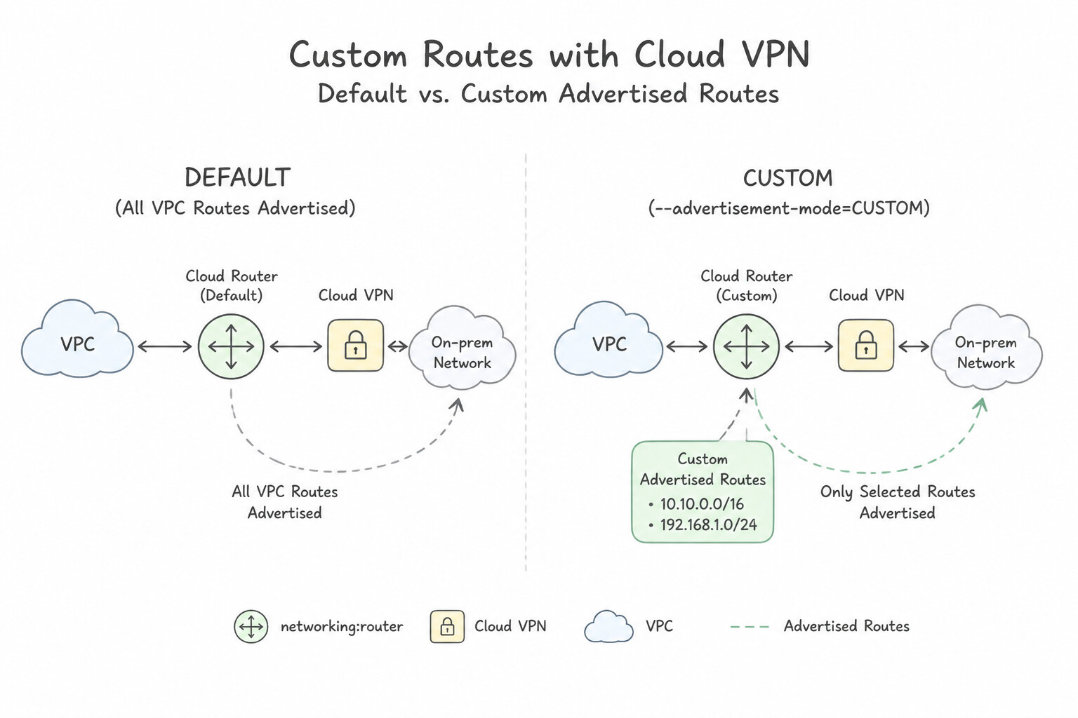
- Default vs. Custom Advertised Routes (
--advertisement-mode=CUSTOM): - By default (
DEFAULTmode), Cloud Router automatically advertises all subnet CIDRs in its region (or all subnets in the VPC if Global Dynamic Routing is enabled). - However, Cloud Router never automatically advertises non-subnet IP ranges! You must enable Custom Route Advertisement (selecting
ALL_SUBNETSplus custom IP ranges) whenever on-premises hosts need to reach: - Private Google Access VIPs (
199.36.153.8/30) or Restricted Google Access VIPs (199.36.153.4/30). - Cloud DNS Outbound Forwarding Source Range (
35.199.192.0/19). - Regional Proxy-Only Subnets (required for Hybrid NEGs health checks and Envoy LBs).
- Private Service Connect (PSC) Endpoint IPs or
/32internal VIPs. - Peered VPC Subnets or Google-Managed Services Ranges (like Cloud SQL / Filestore PSA ranges
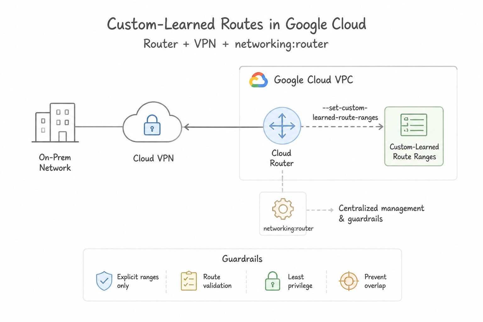
10.x.x.x/16). - Custom-Learned Routes (
--set-custom-learned-route-ranges): - What if an on-premises peer router cannot advertise a specific CIDR via BGP (or you want to override learned prefixes with a specific static prefix), but you still want that route to automatically withdraw if the BGP session goes down?
- Configuring Custom-Learned Routes on a Cloud Router BGP peer instructs Cloud Router to act as if it learned those exact IP prefixes from that BGP peer (with the peer's configured learned route priority). As soon as the BGP session drops, Cloud Router automatically removes the custom-learned routes so traffic fails over to a healthy backup tunnel!
Key Implementation Patterns
- Traffic Engineering with MED on Custom Routes: Use Update the BGP session for Tunnel A to use a lower advertised route priority (MED) than Tunnel B. Lower MED values are preferred in BGP. Setting a lower advertised priority on Tunnel A makes it the primary ingress path.
- Selective Subnet Advertisement: Use Switch the Cloud Router to custom advertisement mode. Add the IP address ranges of the 'frontend' and 'backend' subnets to the advertised routes list. Custom advertisement mode allows you to explicitly select which subnets to advertise, effectively hiding the others.
- Advertising Default Route to On-Premises: Use Update the Cloud Router BGP session to add a custom advertised route for 0.0.0.0/0. Advertising 0.0.0.0/0 via BGP tells the on-premises router to send all internet traffic to Google Cloud. (Avoid alternative: VPC static routes control traffic leaving Google Cloud, not traffic advertisements sent to on-premises routers.)
Key Takeaways (4.3c)
- MED (Multi-Exit Discriminator) is used to influence ingress traffic flow from a peer into your network.
- In Google Cloud Router, MED is configured via Advertised Route Priority.
- Lower MED values indicate a higher preference (primary path).
- Higher MED values indicate a lower preference (backup path).
Consideration 4.3d: Choosing best path selection mode
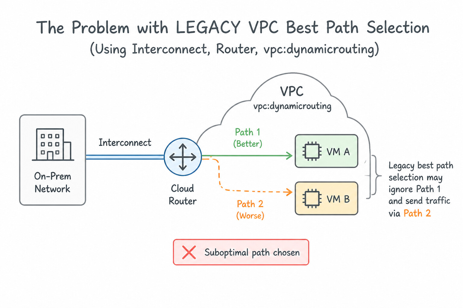
- The Problem with
LEGACYVPC Best Path Selection: - In Google Cloud's
LEGACYbest path selection mode, when a VM inus-east1sends traffic to on-premises (192.168.1.0/24), the VPC routing plane evaluates: - Longest prefix match (
/24beats/16). - Shortest
AS_PATH. - Region-to-Region Cost (Local Region ALWAYS Wins!): A route learned in the same region (
us-east1) is unconditionally preferred over a route learned in a remote region (us-west1), completely ignoring the MED values of the remote region! - Lowest learned priority (
MED). - Real-World Consequence (common pitfalls): Suppose you have a primary Dedicated Interconnect in
us-west1(MED = 50) and a low-bandwidth backup HA VPN inus-east1(MED = 500). UnderLEGACYmode, VMs inus-east1will ignore theus-west1Interconnect (MED 50) and send all traffic out the localus-east1backup HA VPN (MED 500) unless on-premises prependsAS_PATHon theus-east1VPN! - The Solution:
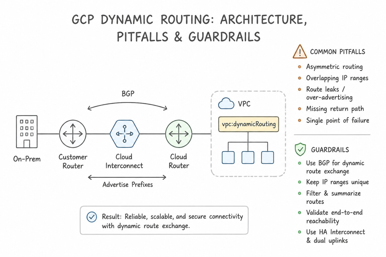
STANDARDBest Path Selection withMULTI_REGIONALCost: - Configure the VPC network with
--bgp-best-path-selection-mode=STANDARDand--bgp-bps-inter-region-cost=ADD_COST_TO_MED. - In
STANDARDmode withADD_COST_TO_MED, Google Cloud adds the deterministic inter-region cost penalty directly to the learnedMEDof remote-region routes (e.g.,us-west1InterconnectMED 50+ inter-region cost208=258), which beats the localus-east1backup VPN (MED 500), allowing VMs inus-east1to prefer the remote high-speed Interconnect without requiringAS_PATHprepending!
Key Implementation Patterns
- Active/Passive Interconnect Configuration via MED: Use Configure the Cloud Router BGP session for the primary link with a lower base advertised route priority (MED) and the backup link with a higher value. Lower MED values indicate higher priority. Configuring the primary link with a lower MED ensures it is preferred over the backup link.
- Global vs. Regional Dynamic Routing: Use Change the VPC network dynamic routing mode to Global. Global dynamic routing enables a Cloud Router to advertise subnets from all regions in the VPC, not just its local region. (Avoid alternative: Cloud Routers must be in the same region as the Interconnect VLAN attachment; cross-region attachment is not supported.)
Key Takeaways (4.3d)
- Active/Passive routing on Cloud Interconnect is achieved using BGP MED values.
- The Cloud Router setting 'Advertised route priority' maps directly to the BGP MED attribute.
- For MED values, a lower number indicates a higher priority (preferred route).
- Consistent MED values across links result in ECMP (Active/Active) routing.
Quick Decision Cheat Sheet (Subsection 4.3)
If the Scenario Requires... | Choose This Google Cloud Pattern | Avoid This Common Mistake |
|---|---|---|
"Dedicated Interconnect Cloud Router ASN" | Must use ASN 16550 | Using 64512 or 65001 (only allowed on HA VPN and Partner Interconnect) |
"Prefer one tunnel over another in the SAME region for traffic FROM Google Cloud TO on-premises" | Advertise a lower MED (or shorter AS_PATH) from the on-premises router on the primary tunnel (or set lower --custom-learned-route-priority on Cloud Router) | Changing the Cloud Router's Advertised Route Priority (that only controls traffic from on-premises to GCP!) |
"Prefer one tunnel over another for traffic FROM on-premises TO Google Cloud" | Set a lower Advertised Route Priority ( MED) on the primary Cloud Router BGP session (e.g., 100 vs 200) | Creating static routes inside the Google Cloud VPC |
"Sub-second hybrid failover (< 1 second) when a tunnel or VLAN drops" | Enable Bidirectional Forwarding Detection (BFD) ( ACTIVE mode, 300ms–1000ms x 3) | Relying on default BGP Keepalive ( 20s) and Hold (60s) timers |
"Advertise Peered VPC subnets or Cloud SQL Private Service Access ( 10.x.x.x) to on-premises" | Configure Custom Advertised Routes on Cloud Router and export custom routes across VPC Peering | Enabling Global Dynamic Routing alone (Cloud Router never auto-advertises peered subnets) |
"Prevent asymmetric routing between two regions with active-passive hybrid links" | Match inbound and outbound symmetry using consistent MED / AS-Path prepending on both Cloud Router advertisements and on-premises advertisements | Enabling ECMP across primary and backup links in different regions |
Further Reading (Subsection 4.3)
- Update the base route priority — This guide explains how to update the advertised route priority (MED) on a Cloud Router to influence ingress traffic flow.
- Cloud Router overview — Provides a high-level overview of Cloud Router features, including route advertisements and priority.
- Best practices for Cloud Router — Refer to the section on 'Advertised prefixes and priorities' which explains how MED values affect route selection and how to configure them for active/active or active/passive scenarios.
- Establishing 99.9% availability for Dedicated Interconnect — This guide discusses topology and BGP configuration, noting that for load balancing, you must configure the same MED values on BGP sessions.
- Advertise custom address ranges — Describes how to specify custom IP address ranges to advertise for a BGP session on Cloud Router.
- Configuring BFD for Cloud Router — Explains how BFD works with BGP sessions on Cloud Router to detect forwarding path failures faster than BGP timers alone.
Subsection 4.4: Configuring Network Connectivity Center
The Big Picture
As enterprise footprints grow beyond a handful of VPCs and branch offices, traditional full-mesh VPC Network Peering hits an architectural brick wall. VPC Network Peering is strictly non-transitive: if spoke-vpc-a peers with transit-hub-vpc, and transit-hub-vpc terminates a Cloud Interconnect or HA VPN from on-premises, spoke-vpc-a can receive custom dynamic routes from the Hub VPC (--export-custom-routes / --import-custom-routes), but if spoke-vpc-a needs to reach spoke-vpc-b through transit-hub-vpc, or if transit-hub-vpc needs to route traffic between two different VPCs without an NVA or NCC, VPC Peering drops the packets. Even worse, VPC Peering shares quota ceilings (such as internal load balancer forwarding rules and subnet route tables) across the peering group.
Network Connectivity Center (NCC) solves this by introducing a centralized control-plane Hub (network-connectivity hubs) to which you attach VPC Spokes, Hybrid Spokes (HA VPN tunnels, Cloud Interconnect VLAN attachments, and Router Appliance VMs), and Producer VPC Spokes. With NCC, you can aggregate dozens or hundreds of VPCs into a Mesh or Star topology, insert third-party SD-WAN or Next-Generation Firewall Router Appliances (RAs) running eBGP with Cloud Router, or enable Site-to-Site Data Transfer (--site-to-site-data-transfer) on Hybrid Spokes so global branch offices use Google's private fiber backbone as an enterprise WAN!
Consideration 4.4a: Creating hybrid spokes
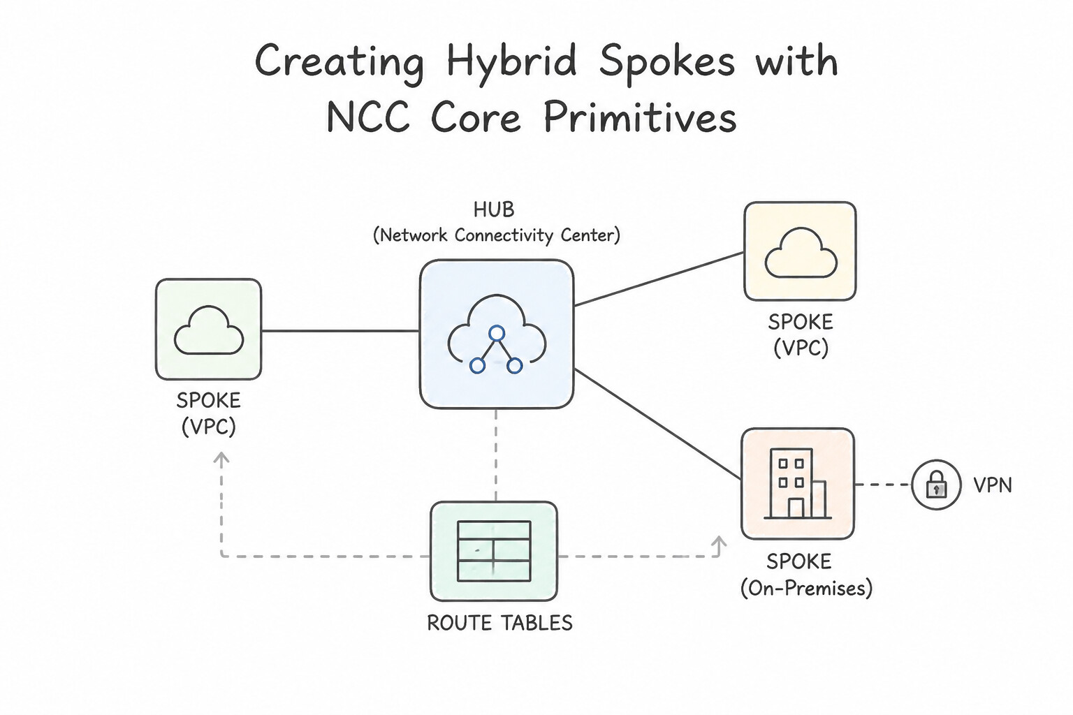
- NCC Core Primitives (Hub, Spokes, and Route Tables):
- An NCC Hub is a global control-plane resource inside a single project (supporting Cross-Project VPC Spokes across your organization).
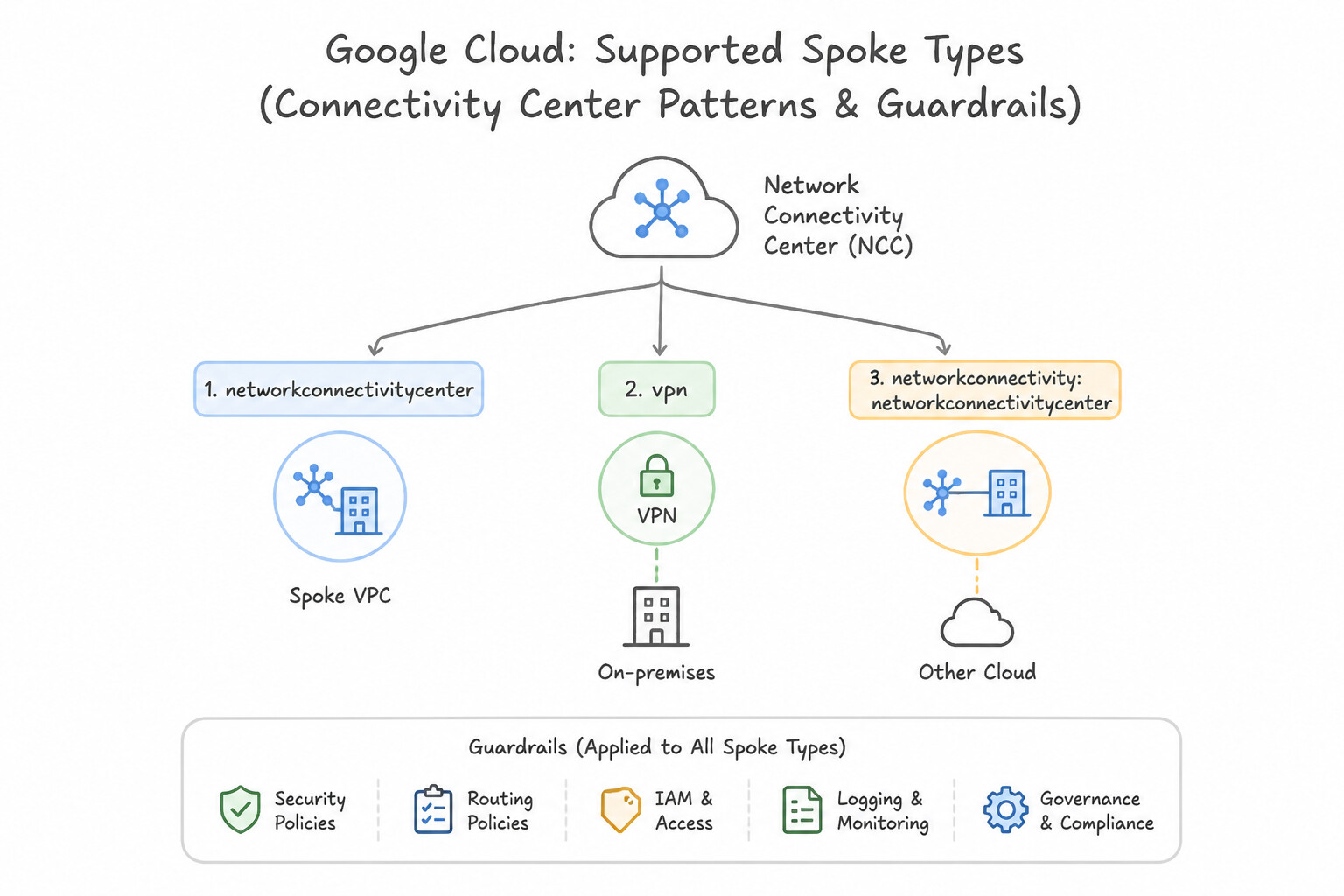
- Supported Spoke Types:
- VPC Spokes: Connect standard VPC networks (local or cross-project) to the Hub to exchange subnet routes (IPv4/IPv6) and dynamic routes (learned from Hybrid Spokes located in a routing VPC).
- Producer VPC Spokes: Expose Google-managed services (like Cloud SQL or Vertex AI deployed via Private Services Access in a peered servicenetworking VPC) to other VPC Spokes on the NCC Hub—solving the classic non-transitive peering gap between NCC spokes and Private Services Access!
- Hybrid Spokes: Attach HA VPN Tunnels, Dedicated/Partner Interconnect VLAN Attachments, or Router Appliance VMs (which all reside inside a designated routing VPC) to the NCC Hub.
- Mesh vs. Star Hub Topologies (
--preset-topology): MESH(Default): Every VPC spoke belongs to thedefaultgroup and has full any-to-any subnet reachability with every other VPC spoke and hybrid spoke.STAR: Splits spokes into two groups:center(e.g., Central Transit / Shared Services VPCs and Hybrid Spokes) andedge(isolated tenant or workload VPCs). Spokes in theedgegroup can communicate withcenterspokes, butedgespokes CANNOT communicate directly with otheredgespokes!
Key Implementation Patterns
- Mapping HA VPN Tunnels to NCC Spokes: Use Create two spokes and attach a VPN tunnel resource to each spoke. NCC requires you to attach individual VPN tunnel resources as spokes to the Hub. (Avoid alternative: NCC spokes wrap specific connectivity resources like tunnels, not the parent gateway resource.)
- Enabling Site-to-Site Data Transfer: Use Update the Network Connectivity Center hub to enable site-to-site data transfer. Spoke-to-spoke communication in NCC requires enabling the 'site-to-site data transfer' feature on the hub. (Avoid alternative: Firewall rules control permissions but do not enable the underlying routing path required for spoke-to-spoke communication.)
- Router Appliance Spoke Configuration: Use Enable IP forwarding on the VM. Configure BGP sessions between the Cloud Router and the VM. Router Appliance spokes require IP forwarding on the VM instance and BGP peering with a Cloud Router. (Avoid alternative: NCC Router Appliance integration uses standard BGP, not a proprietary agent installed on the VM.)
Key Takeaways (4.4a)
- Network Connectivity Center (NCC) uses a Hub and Spoke model.
- A Spoke wraps an underlying connectivity resource.
- For VPNs, the Spoke resource is the VPN Tunnel, not the Gateway or Router.
- For HA VPN, create one spoke per tunnel.
Consideration 4.4b: Establishing site-to-site data transfer
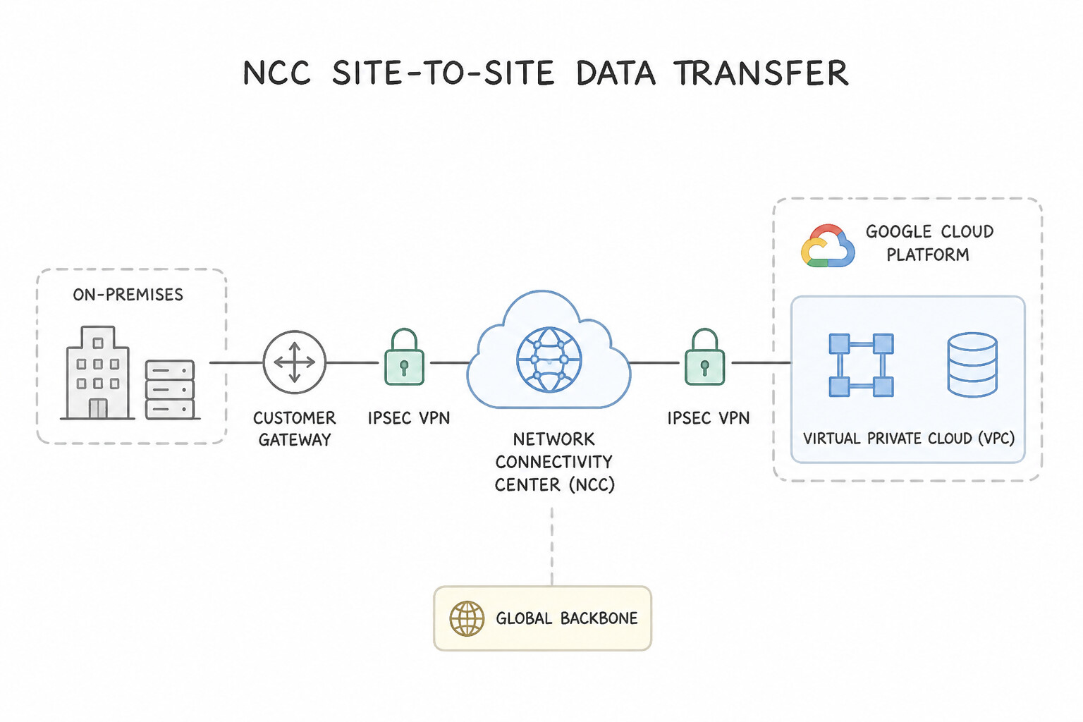
- What is NCC Site-to-Site Data Transfer?:
- Allows two or more external on-premises sites (e.g., a Tokyo branch office connected via HA VPN in
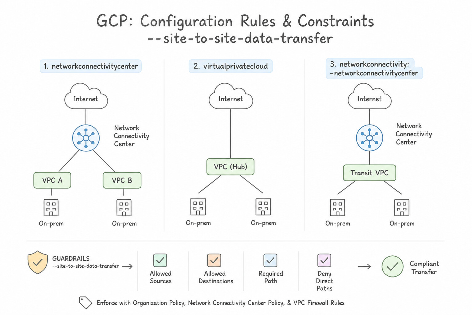
asia-northeast1and a London data center connected via Dedicated Interconnect ineurope-west2) to send traffic directly to each other over Google's global backbone. - Configuration Rules & Constraints (
--site-to-site-data-transfer): - You must attach the HA VPN tunnels, Interconnect VLAN attachments, or Router Appliance instances as Hybrid Spokes to the same NCC Hub and explicitly pass the
--site-to-site-data-transferflag when creating each participating Hybrid Spoke. - Dynamic Route Propagation: Once enabled on Hybrid Spoke A (
asia-northeast1) and Hybrid Spoke B (europe-west2), Cloud Router inasia-northeast1learns the Tokyo prefixes via BGP, publishes them to the NCC Hub route table, and the Cloud Router ineurope-west2automatically re-advertises those Tokyo prefixes over BGP to the London data center! - Global Dynamic Routing Requirement: If the two Hybrid Spokes are in different Google Cloud regions, the underlying routing VPC must have Global Dynamic Routing (
--bgp-routing-mode=GLOBAL) enabled!
Key Implementation Patterns
- Enabling Data Transfer on Router Appliance Spokes: Use Update the Router Appliance spokes to enable site-to-site data transfer. Router Appliance spokes require the 'site-to-site data transfer' flag to be explicitly enabled to allow transit traffic. (Avoid alternative: Global routing affects regional route visibility, not the specific permission for NCC spokes to exchange data.)
- Heterogeneous Spoke Connectivity: Use Create a Network Connectivity Center Hub. Add the Dedicated Interconnect VLAN attachment and the Cloud VPN tunnels as spokes. Enable site-to-site data transfer on the spokes. NCC Hubs allow route exchange between spokes. Attaching both the Interconnect and VPN as spokes and enabling site-to-site data transfer permits direct communication between the external sites.
- Global Site-to-Site Reachability: Use Ensure that the site-to-site data transfer setting is enabled for both spokes. Enabling site-to-site data transfer on NCC spokes allows external sites to communicate over the Google backbone. (Avoid alternative: VPC Network Peering connects VPCs, not the external sites attached via NCC spokes.)
Key Takeaways (4.4b)
- Network Connectivity Center (NCC) allows different network resources (spokes) to connect via a central Hub.
- Router Appliance spokes are used to integrate Network Virtual Appliances (NVAs) like SD-WAN routers into NCC.
- Site-to-site data transfer via the Google backbone is not enabled by default for Router Appliance spokes and must be explicitly toggled on.
- Network Connectivity Center (NCC) uses a Hub and Spoke model to manage connectivity.
Consideration 4.4c: Creating Router Appliances
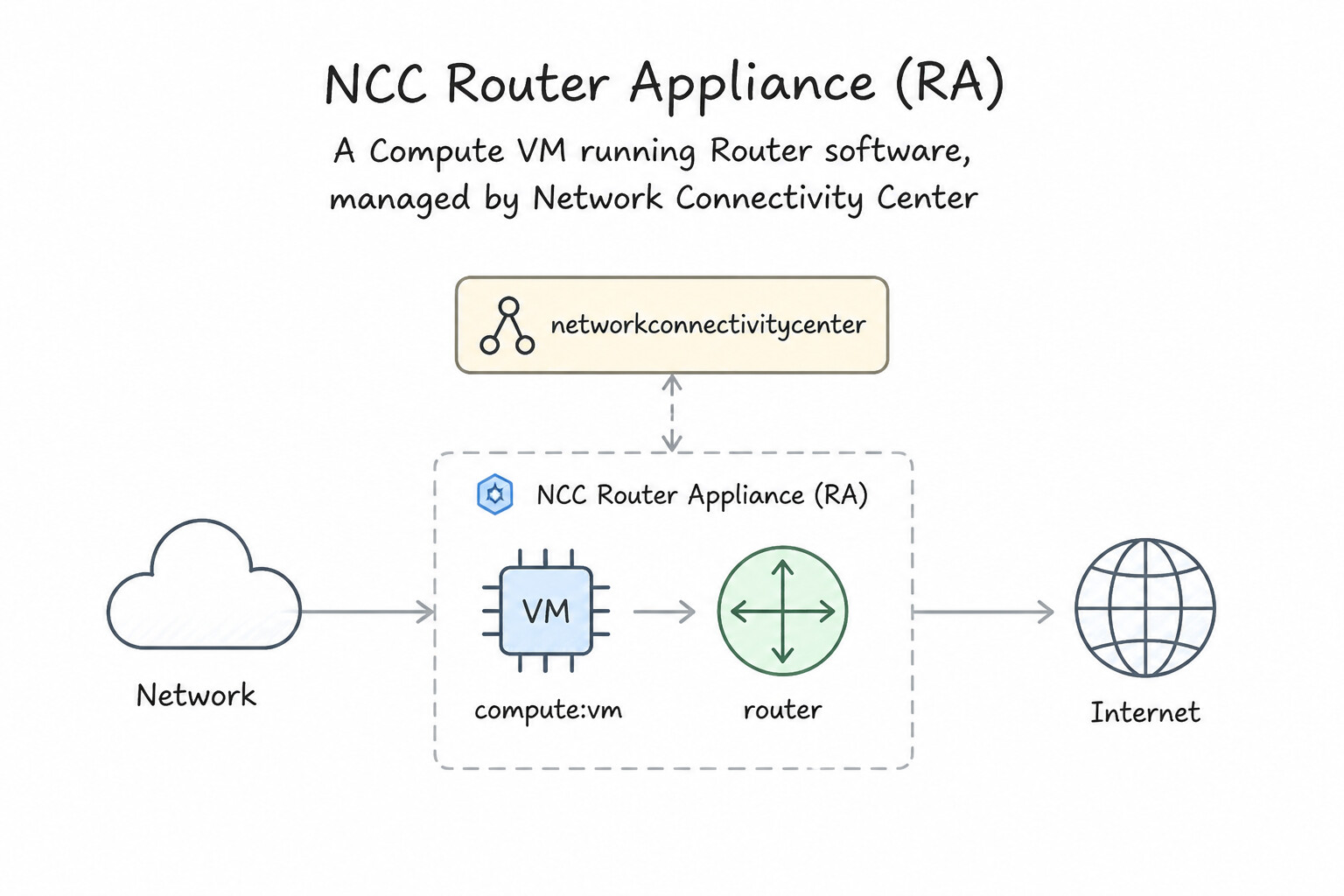
- What is an NCC Router Appliance (RA)?:
- Before NCC Router Appliance existed, Compute Engine VMs running third-party SD-WAN (Cisco Catalyst SD-WAN, Aruba EdgeConnect, Versa) or Next-Generation Firewalls (Palo Alto VM-Series, Fortinet FortiGate) could only insert routes into a VPC via static routes or API scripts—they could never establish a BGP session with Cloud Router.
- An NCC Router Appliance Spoke (
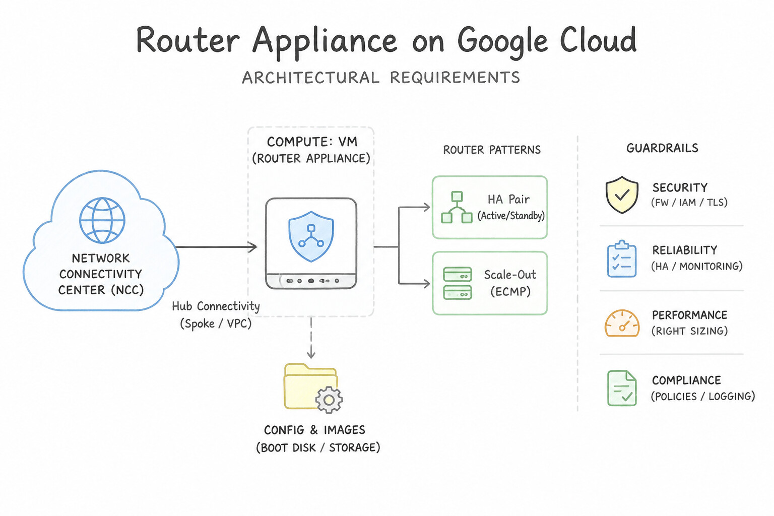
--linked-router-appliance-instances) allows a Cloud Router to establish a direct eBGP session with the internal primary IPv4 address (nic0) of a Compute Engine VM located in the same VPC and the same region! - Architectural Requirements for Router Appliances:
- Enable
--can-ip-forwardon the Router Appliance Compute Engine VM at creation time. - Create two redundant BGP sessions from the regional Cloud Router (using two redundant Router Appliance interfaces / Cloud Router redundant interface IPs in the same subnet) to the Router Appliance VM's internal IP in the same region.
- Allow TCP port
179(BGP) (and UDP3784/3785if using BFD) in the VPC ingress firewall rules between the Cloud Router interface IPs and the Router Appliance VM. - Use Cases:
- Connecting a third-party SD-WAN overlay fabric into Google Cloud with native dynamic BGP route exchange.
- East-West / Hybrid Traffic Hair-Pinning: Advertising summary prefixes (
0.0.0.0/0or10.0.0.0/8) from a pair of NGFW Router Appliance VMs into Cloud Router so traffic between on-premises and VPC subnets is dynamically steered through the firewall appliances.
Key Implementation Patterns
- VM Instance Prerequisite Configuration: Use Enable IP forwarding on the network interface of the VM instance. Router Appliances act as gateways and must have IP forwarding enabled on the VM network interface to handle traffic not destined for the VM itself. (Avoid alternative: Firewall rules control access to ports but do not enable the network interface to forward transit traffic meant for other destinations.)
- Router Appliance Spoke Location Constraints: Use Create the spoke resource in the "europe-west1" region to match the VM location. Router Appliance spokes must be created in the same region as the underlying VM instance. (Avoid alternative: Router Appliance spokes are regional resources, not global, even though the hub is global.)
- BGP Session Establishment Firewalling: Use Create an ingress Virtual Private Cloud (VPC) firewall rule to allow TCP port 179 from the Cloud Router BGP IP address. BGP requires TCP port 179, and Google Cloud firewall rules deny ingress traffic by default, so you must explicitly allow it.
Key Takeaways (4.4c)
- Router Appliances on Google Cloud are essentially Compute Engine VMs running routing software.
- By default, Compute Engine VMs block traffic that is not explicitly sourced from or destined to the VM's assigned IP address.
- You must enable 'IP Forwarding' on the VM instance for it to act as a gateway or router.
- This configuration is set at the infrastructure level (VM settings), not just inside the Guest OS.
Consideration 4.4d: Solving transitivity issues
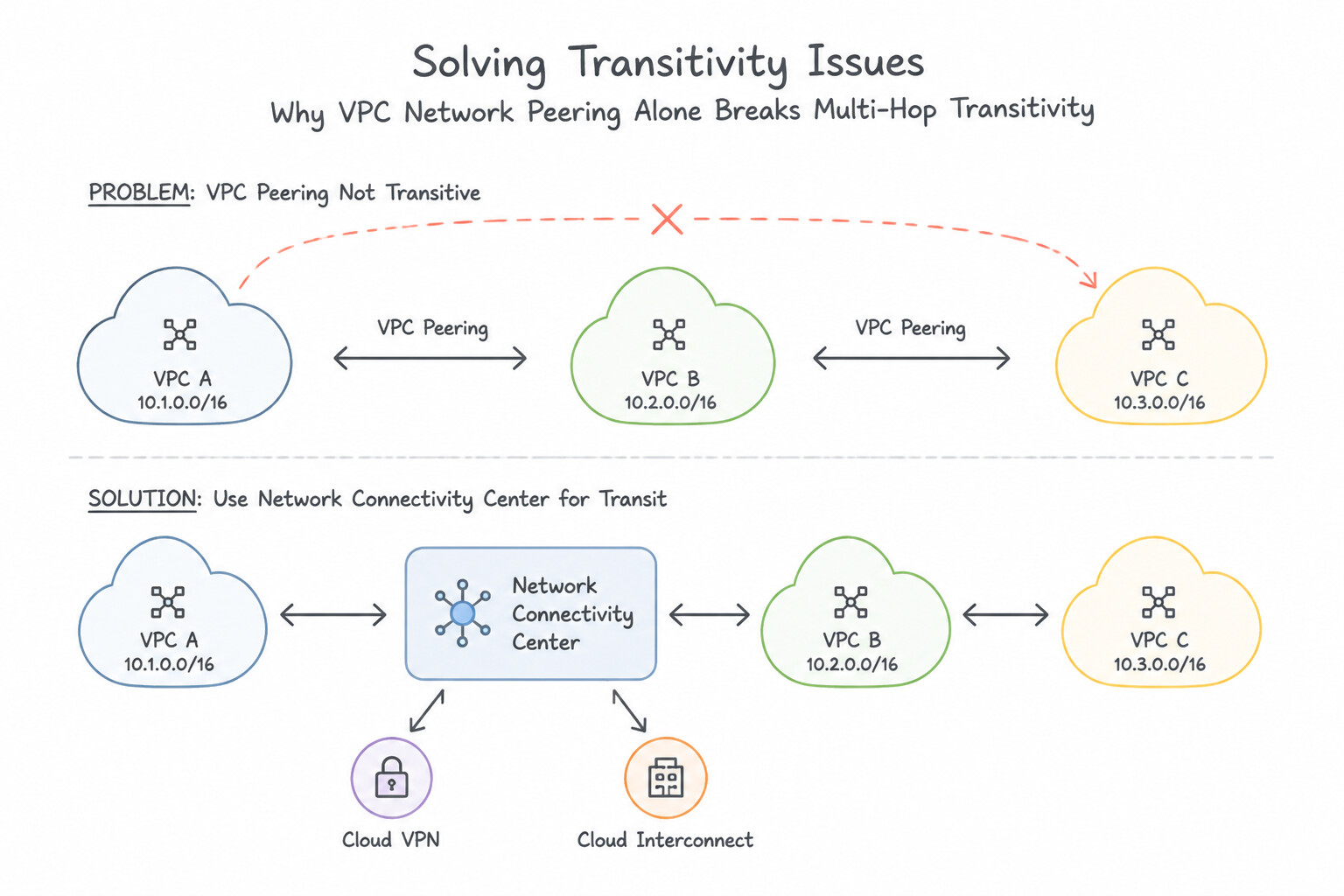
- Why VPC Network Peering Alone Breaks Multi-Hop Transitivity:
- In VPC Network Peering (
VPC-A <-> VPC-B <-> VPC-C),VPC-AandVPC-Cnever exchange subnet or custom routes. - Even when combining HA VPN/Interconnect in
VPC-Bwith VPC Peering toVPC-A(using--export-custom-routesonVPC-Band--import-custom-routesonVPC-A), ifVPC-Ais instead connected toVPC-Bvia NCC VPC Spokes, all VPC Spokes on the NCC Hub automatically learn dynamic routes from Hybrid Spokes on that Hub without managing pairwise VPC Peering custom route flags! - Key NCC Limitations & common pitfalls to Memorize:
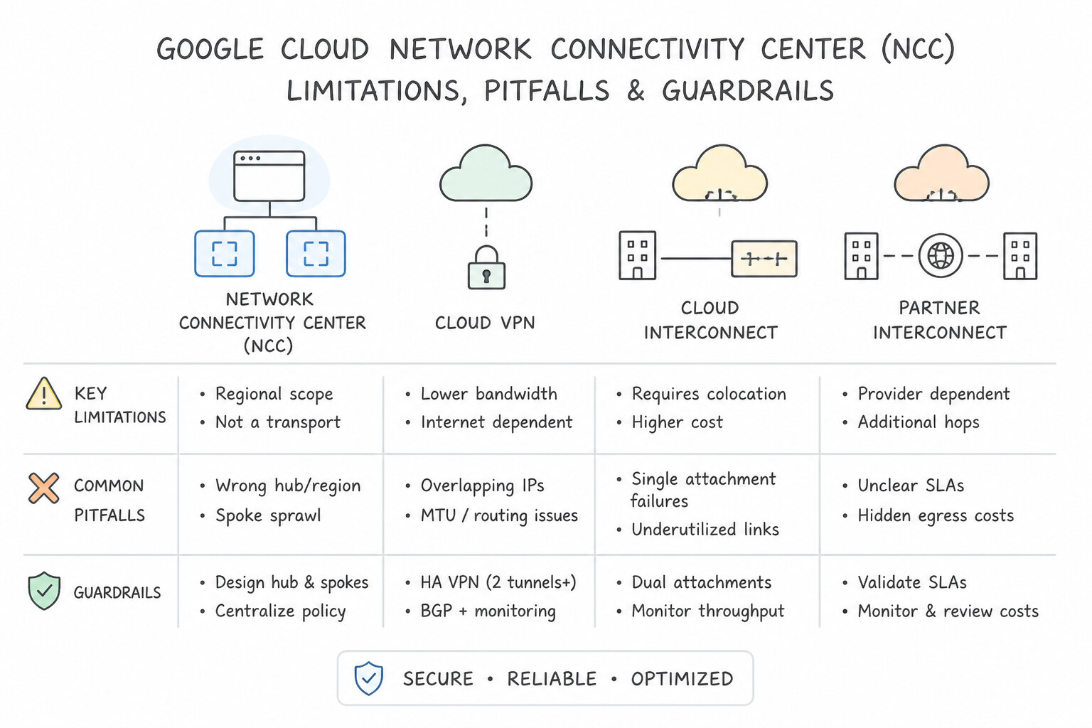
- No VPC Spoke + VPC Peering Chaining: An NCC VPC Spoke cannot transitively bridge routes to another VPC that is only connected via VPC Network Peering (unless that peered network is added as a Producer VPC Spoke for managed services or migrated to a full NCC VPC Spoke).
- Static Routes Are Never Exchanged by NCC: NCC Hubs only exchange VPC subnet routes (from VPC Spokes) and BGP dynamic routes (from Hybrid Spokes). Custom static routes inside a VPC Spoke are never exported to the NCC Hub!
- Avoiding Routing Loops with Router Appliances: When a Router Appliance VM receives traffic from on-premises and forwards it to a VPC destination, ensure the Router Appliance uses a dedicated transit NIC/VPC or proper BGP route filtering (or PBR / SNAT) so the return path or egress path does not loop back into Cloud Router's learned route for the same prefix.
Key Implementation Patterns
- Enabling Site-to-Site Data Transfer: Use Enable site-to-site data transfer on the Network Connectivity Center hub. Enabling site-to-site data transfer on the NCC Hub allows traffic to flow transitively between different on-premises sites connected as spokes. (Avoid alternative: VPC Network Peering connects two VPC networks, not individual VPN gateways or external sites.)
- Integrating Hybrid Connectivity Types: Use Create a Network Connectivity Center Hub. Add the VLAN attachments and VPN tunnels as spokes to the Hub. NCC Hubs allow transit connectivity between different spoke types like VPN and Interconnect. (Avoid alternative: A proxy VM is unmanaged, creates a bottleneck, and adds operational overhead.)
- Router Appliance Spoke for SD-WAN: Use Create an NCC Hub. Configure the NVAs as Router appliance spokes. Establish BGP sessions between the NVAs and the Cloud Router. Router appliance spokes allow NVAs to exchange routes dynamically via BGP with the NCC Hub. (Avoid alternative: VPC Network Peering is non-transitive and does not provide the centralized dynamic routing management required.)
Key Takeaways (4.4d)
- Network Connectivity Center (NCC) centralizes management of network connections using a Hub and Spoke model.
- Standard VPC routing is generally not transitive between external connections.
- To allow traffic between two spokes (like two VPN sites), you must enable 'site-to-site data transfer' on the NCC Hub.
- Network Connectivity Center (NCC) uses a Hub and Spoke model to manage connectivity.
Quick Decision Cheat Sheet (Subsection 4.4)
If the Scenario Requires... | Choose This Google Cloud Pattern | Avoid This Common Mistake |
|---|---|---|
"Third-party SD-WAN or NGFW VM needs to run BGP directly with Google Cloud" | NCC Router Appliance (RA) Spoke + Cloud Router in the same VPC and same region + --can-ip-forward + Allow TCP 179 | Creating an HA VPN tunnel to the VM's internal IP or using a Classic VPN gateway |
"Branch-to-branch / Data-center-to-branch transit over Google's global WAN" | NCC Hybrid Spokes with --site-to-site-data-transfer enabled + Global Dynamic Routing | Standard Cloud Router BGP (does not re-advertise learned hybrid routes to other hybrid peers without NCC) |
"Isolate spoke VPCs from each other while allowing all spokes to reach a central hub VPC" | NCC Hub with STAR topology (center group vs. edge group) | NCC Hub with MESH topology (allows all spokes to talk to all other spokes) |
"NCC VPC Spokes need to reach Cloud SQL / Filestore Private Services Access ( servicenetworking)" | Configure a Producer VPC Spoke on the NCC Hub | Exporting custom routes on VPC Peering alone (doesn't propagate across NCC VPC Spokes without Producer VPC Spoke) |
"VPC Network Peering scale limits (exceeding 25 peered VPCs or ILB forwarding rule peering group limits)" | Migrate to Network Connectivity Center (NCC) VPC Spokes (supports up to 250+ VPC spokes with isolated quota domains) | Chaining multiple VPC Peerings A -> B -> C (violates non-transitivity) |
"Cloud Router BGP session to an NCC Router Appliance VM stays down ( Active/Connect)" | Add a VPC Ingress Firewall Rule allowing TCP port 179 from the Cloud Router redundant interface IPs to the Router Appliance VM | Allowing UDP 500/4500 (Router Appliance uses direct TCP 179 eBGP without IPsec encapsulation) |
Further Reading (Subsection 4.4)
- Network Connectivity Center overview — Explains the Hub and Spoke architecture and lists supported spoke resources including VPN tunnels.
- Route exchange with VPC spokes — Provides step-by-step instructions on creating spokes and explicitly mentions selecting a VPN tunnel.
- Work with hubs and spokes — Provides the specific steps to enable data transfer functionality on a hub.
- Router appliance overview — Explains the concept of using a Network Virtual Appliance (NVA) as a spoke in NCC and the requirement for BGP peering.
- Create router appliance instances — Provides the step-by-step procedure, including enabling IP forwarding and configuring BGP sessions.
- Site-to-site data transfer overview — Details specifically how NCC facilitates data transfer between on-premises locations using Google's backbone.
Book TOC · Previous · Chapter 5 of 8 · Next
AwesomeGCP.com Learning
The approach taken is a question-led learning approach: you explore realistic project scenarios where you need to make decisions or take actions to achieve business goals within specific constraints. Instead of passive learning, you are challenged to think and work through the options to master the Professional Cloud Network Engineer (PCNE) certification!